Browse Author

Luke Warby

How to route calls via prefixes on the 2N VoiceBlue Next

If you are using prefixes from your PBX in order to route out via different SIM cards you need to configure the voiceblue to be expecting this. The first thing you will need to do is assign the SIM cards to a GSM group. In this blog it’s configured for two SIM cards/prefixes.

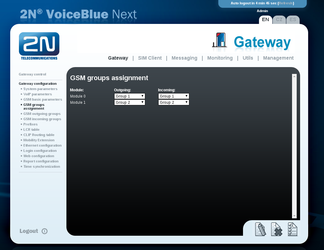
1. In the web user interface go to Gateway configuration > GSM group assignment and set each module to have their own group and press save.

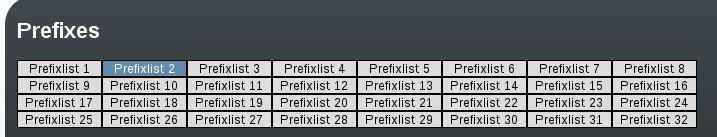
2. Now we need to configure the prefixes that the voiceblue needs to be looking out for when a call gets sent to it. Under “Gateway configuration” go to “Prefixes” and then select one of the prefix tabs along the top.

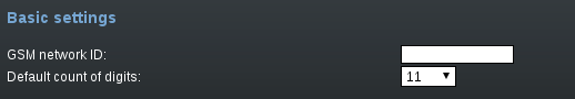
2b) Once you’ve selected one of the Prefixlists we need to set the “Default count of digits” to the digit length we will be sending out via the SIM card and not how many are being sent to the voiceblue via the pbx. Example the voiceblue receives 12 digits and sends out 11 to the mobile network.

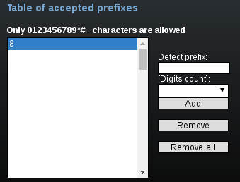
2c) Then we need to configure the table of accepted prefixes. This configures what prefix the voiceblue is looking for. In the “Detect prefix” field enter the desired prefix you are using then press “Add”. It should then appear in the list.

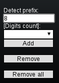
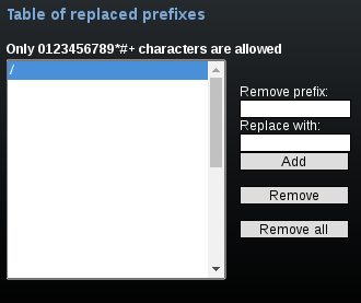
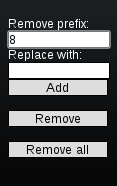
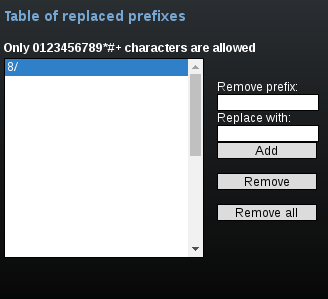
2d) Then we need to configure the “Table of replaced prefixes”. When the “/” is highlighted click the “Remove” button. Once removed in the “Remove prefix” field enter the desired prefix you are using and click the “add” button. Example: it should appear in the list as “8/”

2e) Once you’ve configured the above press save at the bottom and repeat for each prefix being used but remember to use a different list.

3a) Now we need to configure the LCR table. Go to “Gateway configuration” > “LCR table” and configure the first VoIP LCR by clicking the edit button.

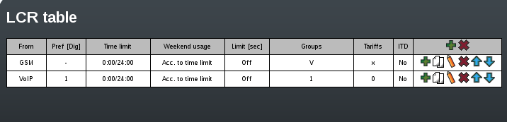
3b) Then select the prefixlist that is going to be used for the first SIM group by editing “prefixlist or number of digits” with the prefixlist tab you configured earlier.

3c) We now need to configure the SIM group by going to “Groups/Tariffs” and selecting the required GSM group we created earlier.

3d) Press the OK button and then save the settings.

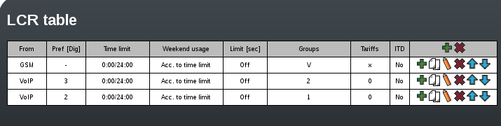
3e) Press the copy button for the VoIP LCR we just edited and then edit the prefixlist and GSM group as before for the second SIM routing and press OK and Save.

4) You should now be able to make calls via the desired SIM using prefixes on the voiceblue next.

Yealink W52P & RTX 4002P – Setting up Daisy Chain

Yealink W52P & RTX 4002P – Setting up Daisy Chain

*RTX4022P can not be set up in Daisy Chain with 3rd party devices such as Gigaset and Yealink*

* Requires RTX PC Software *
* Maximum of 3 Repeaters in a Daisy Chain *

1) Enable Repeater mode on the W52P:

– Press OK on the W52H ‘handset’ and then go to settings. Choose “System Settings” and then select “Repeater Mode”.

2) Pair the first RTX repeater in the chain to the base:

– Plug in the RTX repeater for 1-5 seconds (We count to 3) and then unplug it.

– Plug it in again and leave it. The LED indicator on the RTX repeater will then flash slowly (This means the repeater is ready for manual registration).

– Press the paging key on the W52P base until the “Handset” LED light on the base starts flashing.

– The LED on the RTX repeater will now change to flash faster than it did before.

3) Assign a repeater number to the RTX repeater from 2 to 7, for up to 6 repeaters. (The W52P takes repeater number 1)

– Dial #*9 on the W52H ‘Handset’, it will stay on this call for the duration of this procedure. The LED on the repeater will be lit solid.

– Press a number between 2 and 7. The LED indicator on the repeater will flash a corresponding number of times and then stay solid.

– Accept the registration by pressing the * key and end the call on the W52H ‘Handset’.

4) Configure the repeater:

– Connect this repeater to the RTX USB cable, power supply and your PC.

– Load the RTX software on the supplied CD.

– Select the COM port the USB cable is connected to.

– Press the “load” button.

– Write down the “RFPI” number from the “Repeater” section.

– Disconnect this repeater but do not close the software.

4.1) Configure the next repeaters

– Connect the next repeater that will be used in the daisy chain.

– Type the “RFPI” number you have written down into the “RFPI” box in the “Network Device” section.

– Tick the “Ignore Hop Control” box and optionally the “Monitor Beep” if you want that on (useful for testing).

– Increment the “RPN” number in the “Repeater” section. This need to go up by one for each repeater in this chain.

– Press “Save”.

– If this isn’t the last repeater in the chain, click “Load” and write down the “RFPI” number from the “Repeater” section (This will then be used by the next repeater in the chain in it’s “Network Device” section).

– Pair this repeater to the base by following the procedure in steps 2) & 3).

* Repeat step 4.1) for each repeater in this chain.

* Repeat steps 2) to 4.1) for each chain.

How to put RTX 8630 base in to multi-cell mode

1) Find the IP address of the base unit and enter that in to a web browser to configure the device.

2) Once you have logged in (Default username and password are both admin) go to “Time” on the left hand column and enter a timeserver in the field. Once you have done this click save and reboot. (a reboot is required to work correctly)

3) Now go to “Servers” (This is where we configure the PBX details and tell the extensions where to register). Enter the relevant information in to the fields and then click save.

4) Next go to “Extensions”, click “add extension” and fill in the relevant information for the extension such as authentication name and password. Don’t forget to choose the server we created otherwise the extension will not register.

5) Next go to “Multi cell” and change “Multi cell system” to “Enabled”, then create a “system chain ID” all the bases that are going to be paired need to have the same ID number. The Synchronization time can be increased/decreased to change how often the bases sync together. Leave “Multi cell debug” set to “None” for general use (only change when you need to debug issues) then click save and reboot.

Once the base has rebooted on the “Home/Status” page it should come online as Multi cell Unchained(Unchained) Allowed to Join as Primary

6) Connect the second base and follow step 1, 2, 5. (Repeat for every base being connected)

7) Once the second base has rebooted, on the “Home/Status” page  it should come online as Multi cell Unchained(Unchained) Allowed to Join as Secondary. Wait a few minuets and let the bases communicate with each other.

8) On both bases it should now look different under “Multi Cell”. The base with the extension should be listed as the “primary” and the other base/s should be “locked” under “DECT property”.

Please note: if your base has been displaying (UnchainedAllowed to Join as Secondary) for a while make sure you have created at least 1 extension on the primary base.

Algo Multicast Group

I think nearly anyone that has seen the Algo audio alerting devices has wondered what a group of them would sound like when they are positioned together.

Recently here at ProVu we got to group 38 Algo devices together and set them up to listen on multicast.

We were impressed with the kit and the result, the audio setting was left untouched so they are set to the default (I think it is 4 and goes up to 10) so they can become louder if required.

What do you think?

Check out the video below.

How to set-up JPEG stream on an IP bold door entry for a Snom 760

Here is a guide on how to set up a Snom 760 to be able to view the video stream from a Alphatech IP bold door entry unit.

1. Log in to the web user interface of the Snom 760

2. Go to Function keys

3. Select a key to active the video stream and set the fields to the following

Context —> Active
Type —–> Action URL
Number —-> http://IPADDRESSOFBOLD/snom01.xml ,
Short text —-> Description of button.

4. Once the following fields have been set click apply and then save.

5. To view the stream go to the Snom 760 and press the function key that has been assigned to active the stream of the video.

5b. To stop the stream press the X button on the Snom 760.

How to guide – Pairing Konftel 300Wx to an N300IP

The Konftel 300Wx can be paired with a Gigaset N300IP as a gap compatible device. This will allow the Konftel 300Wx to make and receive calls via the N300IP. Please note that the 300Wx does not bridge conference calls and it is unable to transfer calls. The N300IP allows the 300Wx to connect to VoIP and/or a fixed line. Below is a simple setup guide of how to pair the N300IP and 300Wx:

How to put the Konftel 300Wx in to registration (Pairing) mode

1) Power on the Konftel 300Wx

2) Once the device has booted press the settings key (it is a symbol of a cog)

3) Scroll down to “settings” and then press OK

4) Once in the settings section select “DECT”

(Before continuing to the next step, put the N300IP in to registration mode)

5) Once in “DECT” Select “Register” and then choose the base you would like to pair the Konftel 300Wx up to.

6) Once the base has been selected enter the “pin code” and then wait for the Konftel and the N300IP to pair.

(The pin code is what you enter to access the WUI of the base).

How to put the N300IP in to registration (pairing) mode using the WUI

Note – You can also pair the Konftel to the base by holding the pair button on the front of the N300 when the Konftel is in registration mode

1) Power on the N300IP

2) Log in to the web user interface for the N300IP

3) Click the “Settings” tab on the WUI of the N300IP and then select “Management”

4) Under “Management” select “Miscellaneous”

5) On the “Miscellaneous” page select “Start registration”

6) After selecting “Start registration” put the Konftel 300Wx in to register mode.

Number Assignment

1) Once the Konftel has paired to the base, log in to the web user interface of the N300IP

2) Once logged in to the WUI click the “Settings” tab and select “Telephony” and then “Number Assignment”

3) Once the “Number Assignment” page has loaded you can rename the INT slot that the Konftel has been assigned and you can also choose which connection (extension) the Konftel will use to make and receive calls.

IMPORTANT NOTE – In order for the N300IP and Konftel 300Wx to work properly you will need to turn “ECO Mode+” off. (If this setting is turned on, after a while the Konftel 300Wx loses connection to the base)

“Eco Mode+” can be found in “Miscellaneous” on the WUI of the N300IP