We are thrilled to share that Two-Factor Authentication (2FA) has now been enabled on our reseller portal, ProSys. Security is our priority and we’re delighted to add this latest development to the platform.
Get Two-Factor Authentication (2FA) Enabled on ProSys
2FA can be enabled in two ways:
Your company administrator can enforce 2FA for all users in your organisation. If this has been enabled for your account, you may already have been prompted to set this up when logging in, or you will be asked to do so the next time you sign in.
Alternatively, you can enable 2FA yourself via the Settings page, found under the user icon in the top-right corner of ProSys.
Setup is quick and can be completed using either an Authenticator app or email verification.
Yet to Discover the Power of ProSys?
There are many reasons why our customers use ProSys for their orders. You can:
Access live stock and pricing information
Place your orders online
Apply configuration settings to phones and routers
Access invoice history
Remotely manage devices post deployment
and much more!
With ProSys, we make ordering and managing your devices a simple, seamless process.
Interested in Finding Out More About our Reseller Portal?
ProSys is maintained and developed in house by our own developers. If there’s a new feature or functionality you’d like to see us implement, we’re always listening.
It is still possible to access the old-style web user interface of the D862 and D865 by navigating to the IP address of your phone with “http” and port “3112”:
Example: http://192.168.1.15:3112
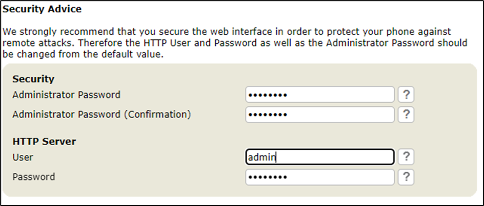
Securing the old-style interface
Once you have accessed the old-style web user interface, it will display security advice where you can setup a HTTP user, HTTP Password and an administrator password to secure your device. If you accidentally navigate away from this page, you can go to ‘Advanced > QoS/Security’ and configure these settings from there:
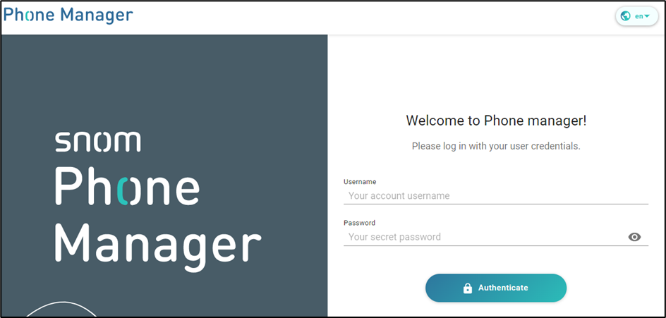
How to login to the new web user interface and secure it.
You’ve received your new Snom phone, you’ve plugged it into the network, it has obtained its IP address. You enter this into your web browser and you are presented with this login page. There’s no default username or passwords here so go ahead and click the ‘Authenticate’ button to login.
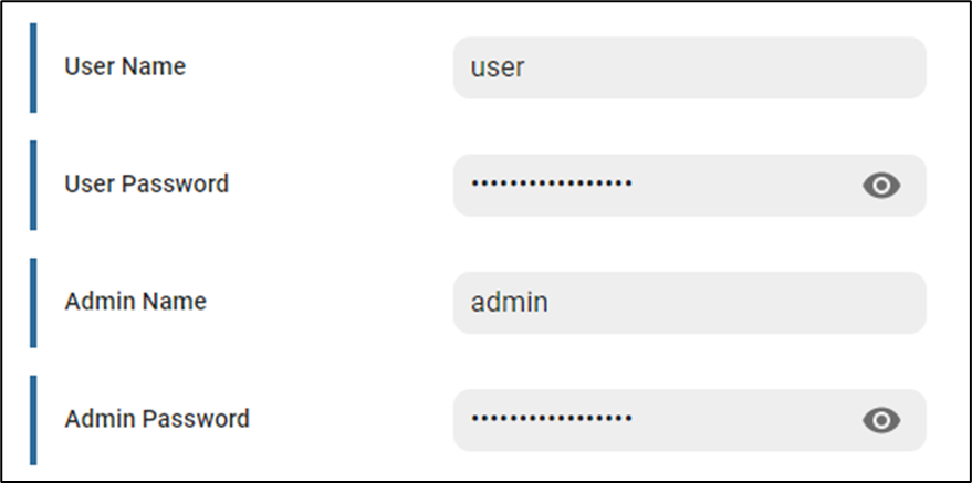
Once logged in, you will see some warnings saying a password has not been set for the ‘admin’ and ‘user’ account. To configure these, go to ‘Security > Advanced’ and populate the fields below and click ‘Apply’.
New provisioning parameters for a new interface
Due to the Snom D862 and D865 having a new web user interface to manage the devices, there are also new provisioning parameters to secure them.
Turning off admin mode will restrict unauthorised access to admin settings such as performing a factory reset, changing SIP credentials etc.
Web user interface method
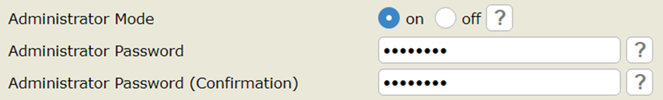
To turn admin mode ‘off’ via the web user interface go to ‘Advanced > QoS/Security’ and set “Administrator mode” to ‘off’ and click ‘save’. – Default pin is ‘0000’ but ensure this is changed to secure your phone even further.
Phone user interface method
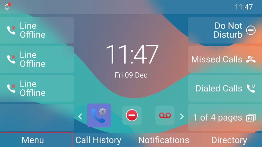
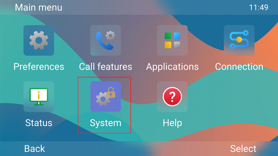
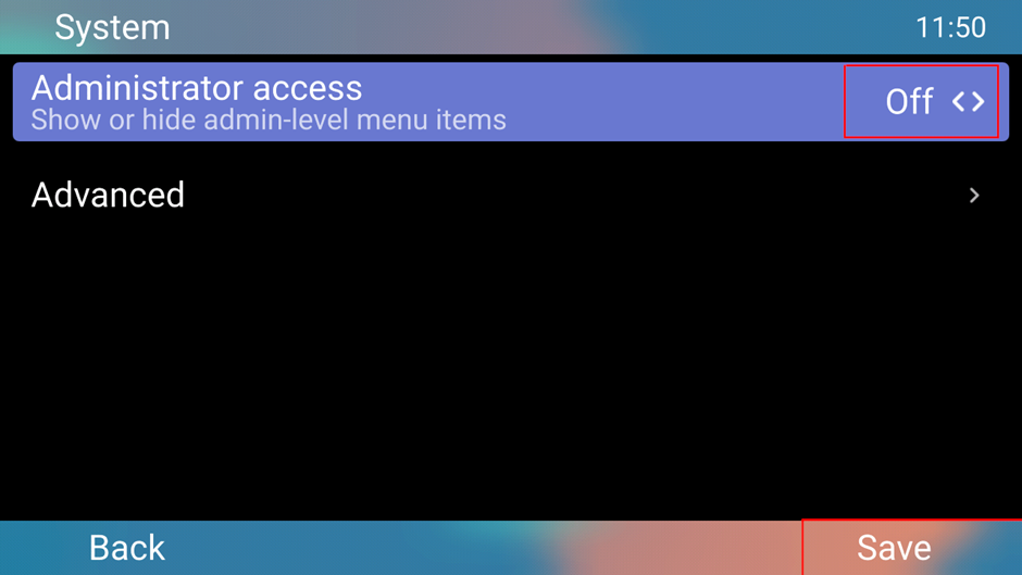
You can turn ‘admin’ mode off on the phone user interface by accessing the following:
‘Menu > System > Administrator Access = Off > Save’
I hope this blog helps you to get started with your new devices. If you need any further support with the new Snom D8xx series, please contact us on: 01484 840048, our support team will be happy to help you with any queries you may have.
If desired on your Yealink Teams phone you can set a screen lock to prevent unauthorized people from making changes to your device, scheduled meetings or prevent them from making outbound calls. When the screen is locked you can still answer incoming calls.
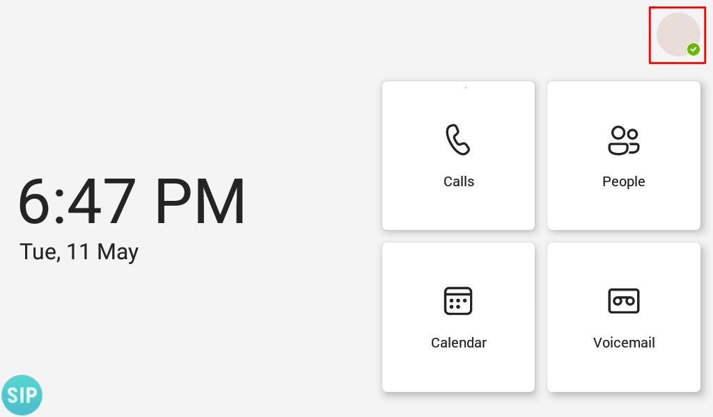
Step 1 – Press your account icon in the top right hand corner where it shows your account’s presence status
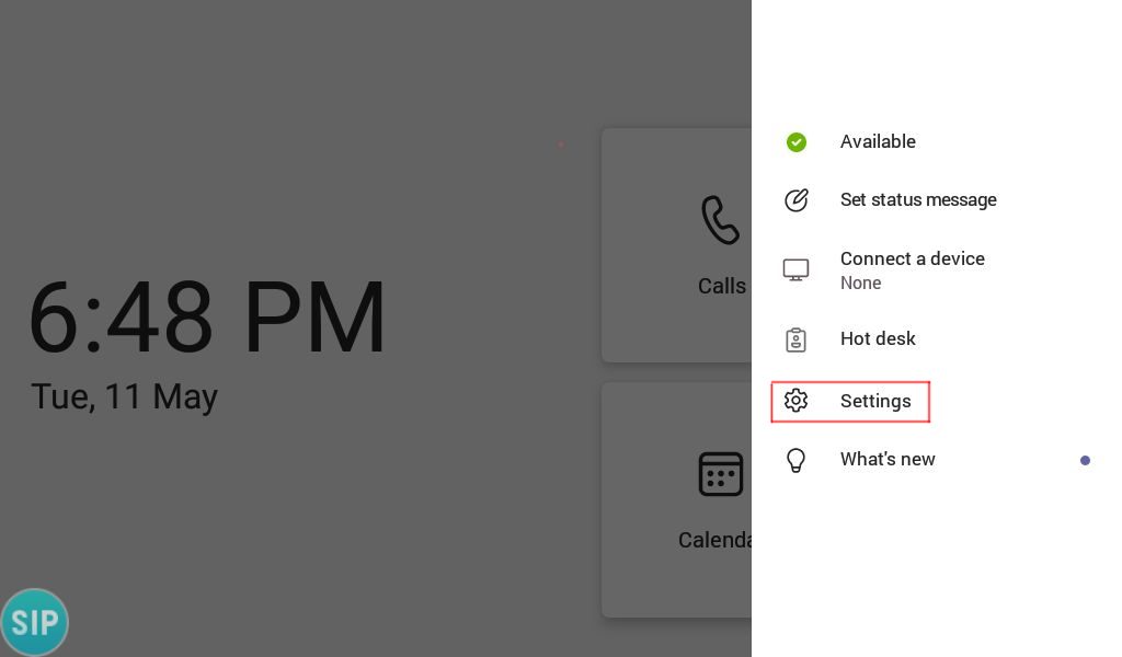
Step 2 – Select ‘Settings’
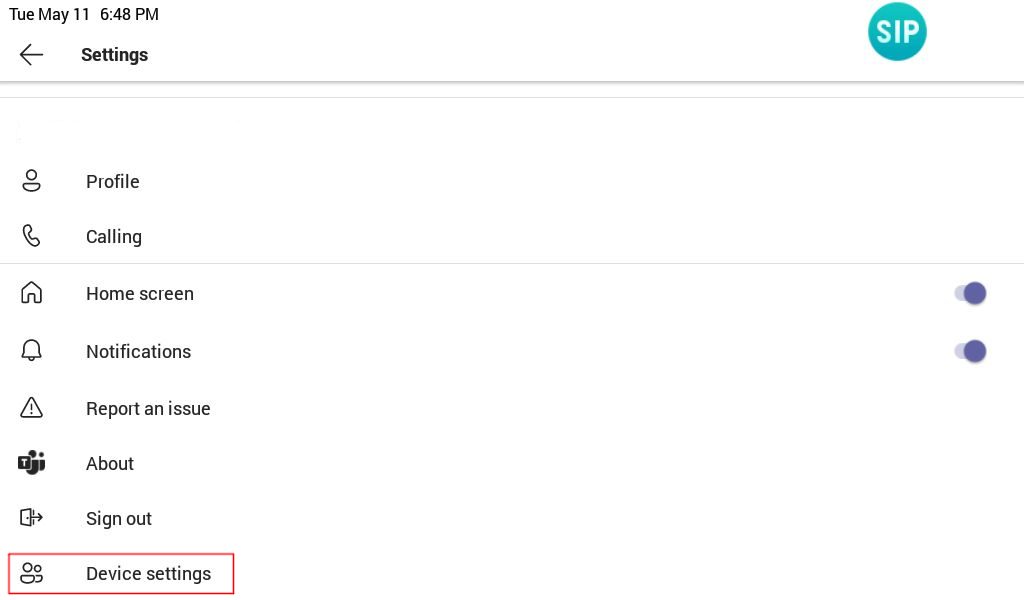
Step 3 – On the settings page scroll down and select ‘Device Settings’
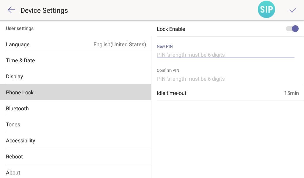
Step 4 – On the ‘device settings’ page find ‘Phone Lock’ and move ‘Lock Enable’ to the ‘ON’ position. Once you have done that enter a PIN with the minimum length of 6 digits, and then enter the digits again to confirm them. You may also wish to decrease the idle time-out to something less that 15 minutes as there’s no way to manually lock the device.
Step 5 – When your phone screen locks it should change to the one shown in the image below, press the padlock icon and enter your pin to unlock to the device.
If you would like to disable screen lock, go to ‘Settings’ > ‘Device Settings’ and change ‘Phone Lock’ to disabled. If your device is forcibly being set with a screen lock you must speak to your system administrator about getting it disabled.
If you have purchased your Yealink Team’s devices from ProVu and you are having difficulty with this blog post, or anything else related to your device please send an email to support@provu.co.uk explaining your issue.
The following blog post was done with a T56A running firmware version 58.15.0.124. The same steps should apply to the following models on the latest firmware version: T55A, T56A, T58A, CP960, MP54, MP56, MP58
You can enable hybrid mode directly through the web user interface of the Teams device. This allows you to use a SIP account to make and receive calls, as well as using your Teams account.
Part 1 – Enable Hybrid mode
Step 1 – Access the web user interface of the phone by entering the IP address of the device in to a web browser. You need to specify ‘https’ and port ‘443’, (Example: https://192.168.1.15:443) in order for the login page to load otherwise you will see an error saying this site cannot be reached.
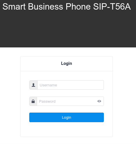
Step 2 – Once you are presented with the login page for the web user interface, login to the device. By default the credentials are ‘admin’ for the username and password.
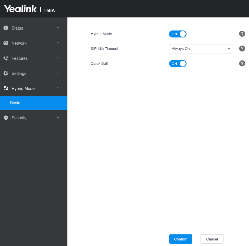
Step 3 – Select Hybrid mode down the column to the left and choose basic. When the page loads move the ‘Hybrid Mode’ slider to ‘ON’.
You will then be presented with two settings, SIP Idle timeout and Quick Ball. The SIP Idle timeout configures if the device should revert back to teams mode after a period of inactivity. The Quick Ball mode is a handy setting that when enabled presents a little button on the screen to flick between teams mode and Hybrid (SIP) mode.
Step 4 – Once you are happy with the settings picked click confirm and the phone will restart.
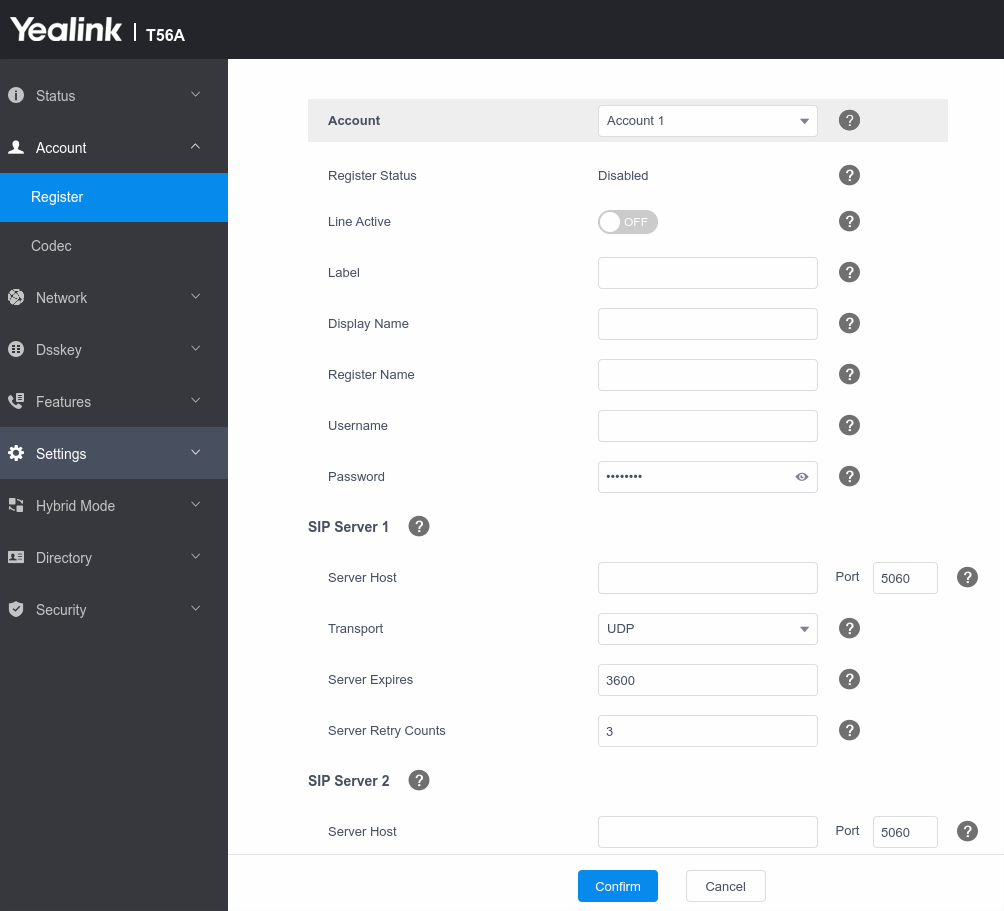
Step – 5 Once the phone has restarted login to the web user interface and click ‘Account’ to setup your SIP account on this device.
Note: If you have Quick Ball turned off, you will need to follow the steps below to access Hybrid mode from the phone user interface otherwise you can easily flick between the two modes via the Quick Ball.
Part 2 – Access SIP (Hybrid mode) from the Phone User Interface
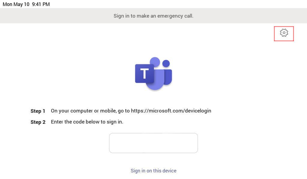
Step 1 – From the settings menu go to ‘device settings’, or when on the sign in screen click the cog symbol highlighted in the image below.
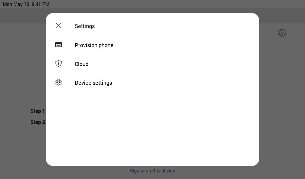
Step 2 – When the new page opens click ‘Device settings’
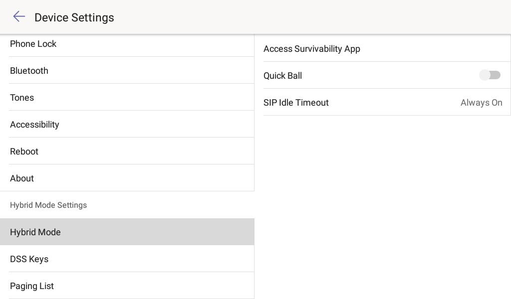
Step 3 – Once on the ‘device settings’ page scroll down to ‘Hybrid Mode’ and you should see the page as shown in the image below. To proceed to access ‘Hybrid mode’ click ‘Access Survivability App’
If you would like to quickly switch between your teams and SIP account I would recommend turning on the Quick Ball feature. This will allow you to change between Teams mode and Hybrid mode at the click of a button. The ‘SIP Idle timeout’ configures if the device should revert back to teams mode after a period of inactivity.
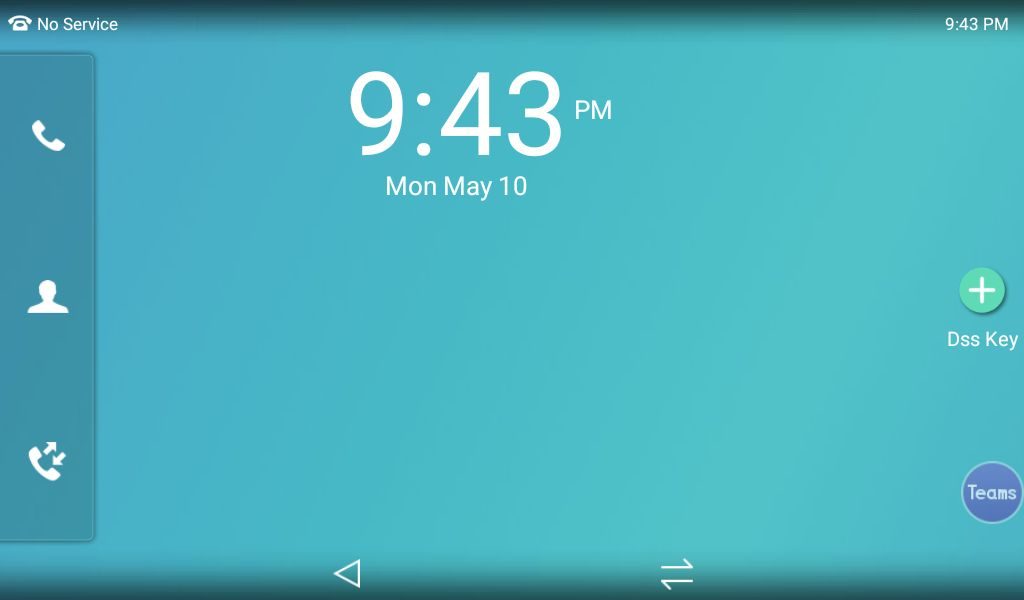
Step 4 – Once you have clicked Survivability you will see a similar screen to the one below and if you have an account registered you can start placing and receiving calls.
In the image below you can see a little circle in the bottom right corner saying teams. This is the Quick Ball to easily change modes, otherwise press the two lines at the bottom of the screen to go back to teams mode and follow the steps above to get back in to hybrid mode.
If you have purchased your Yealink Team’s devices from ProVu and you are having difficulty with this blog post, or anything else related to your device please send an email to support@provu.co.uk explaining your issue.
This blog post was created with a T56A on firmware version 58.15.0.124 but the process should be the same across all Teams desk phones. In order to login to a Yealink Teams device, you need a certain subscription as outlined in this blog post.
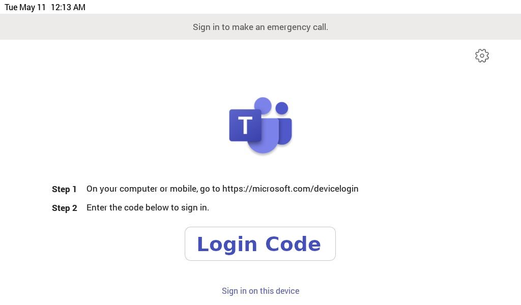
Method 1 – Using an internet capable device with a login code
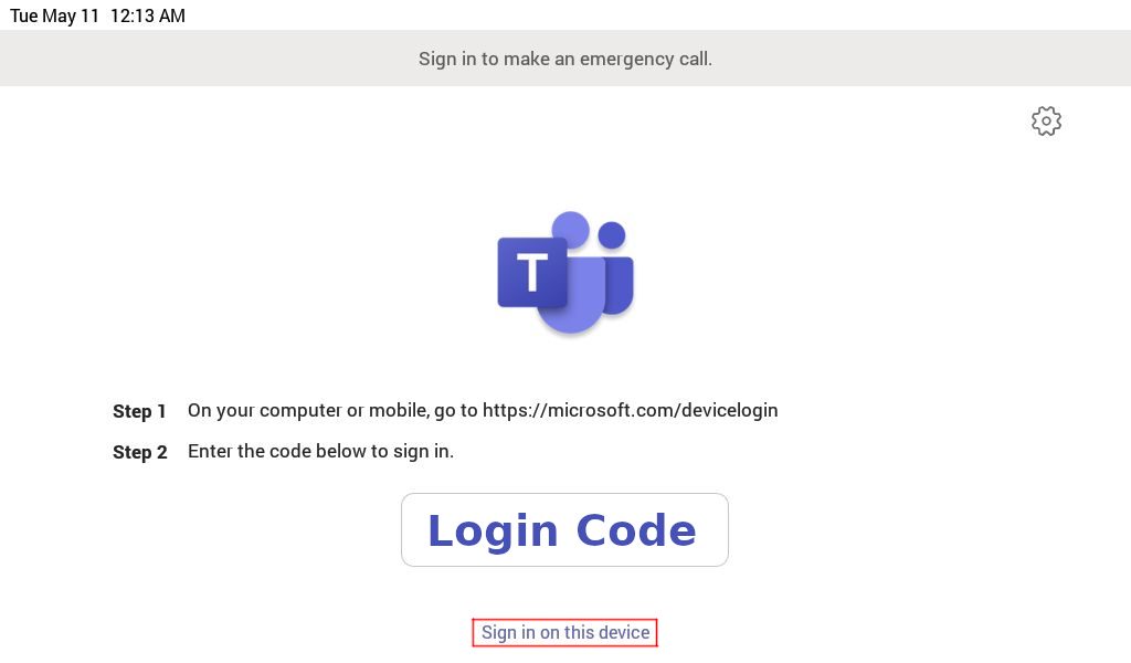
Step 1 – Follow the instructions on the login page of your Yealink Teams device, example shown in the image below, it tells you to web browse to the following URL on an internet capable device: https://microsoft.com/devicelogin
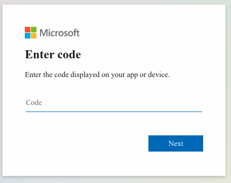
Step 2 – Once you’ve browsed to that URL enter your login code from your devices login screen.
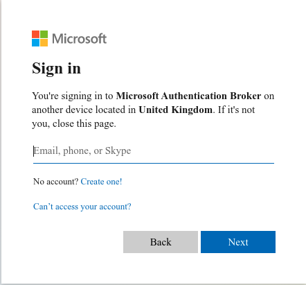
Step 3 – Once you’ve entered the code, you will be presented with a page to enter your email address.
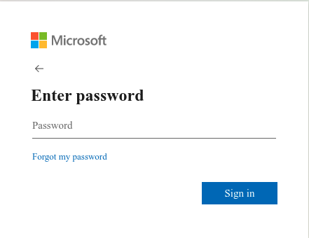
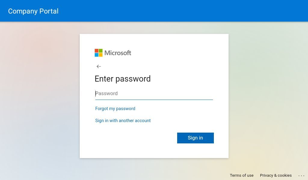
Step 4 – Once you’ve entered your email address, you will then be asked to enter your password for this account.
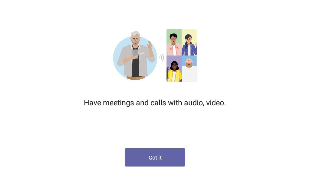
Step 5 – Once you have done that, your phone will automatically sign-in to your teams account and the web page will tell you to close the page. If your phone is nearby you may see it automatically start to log you in and then your phone will display this page. Click ‘Got it’ to start making or receiving calls.
Method 2 – Using the phones user interface
Step 1 – On the device’s login page, press “Sign in on this device”
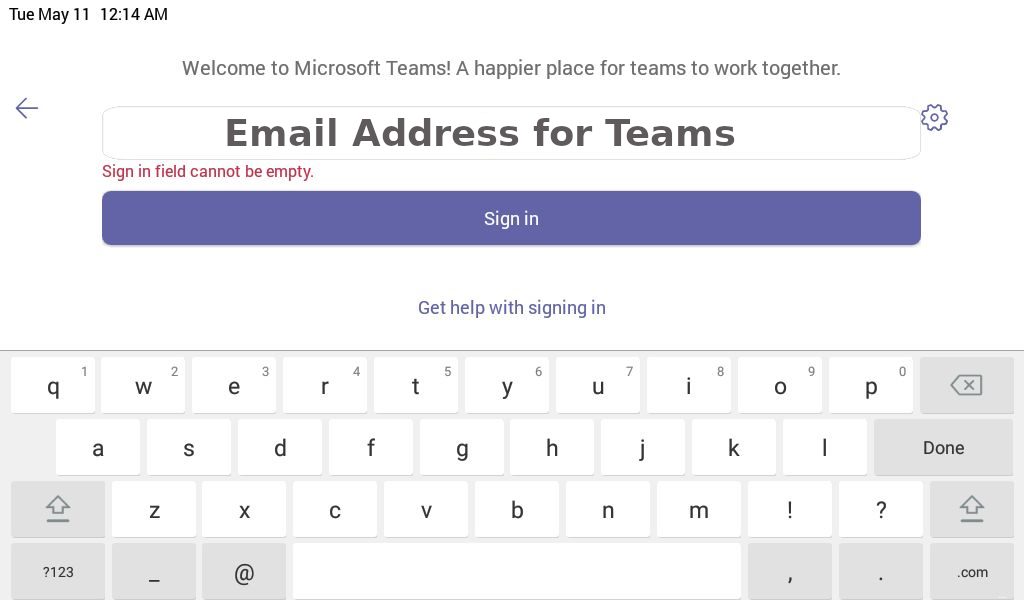
Step 2 – Once you have done that a new screen will load asking for your to enter your Microsoft Teams email address, Once you have done that click the sign in button.
Step 3 – Another screen will then load asking you to enter the password for the Microsoft Teams account you are trying to sign in with.
Step 4 – Once you have done that, it will cycle through some more screens and eventually, it will have signed in to your Teams account on this device. Click ‘Got it’ and you can start to make and receive calls.
If you have purchased your Yealink Team’s devices from ProVu and you are having difficulty with this blog post, or anything else related to your device please send an email to support@provu.co.uk explaining your issue.
At the time of writing, and to the best of our knowledge these are the requirements to be able to log in to a Yealink Teams device with a Microsoft Teams account.
You will need one of the following Microsoft subscriptions, but these do not allow PSTN calling. It’s only possible to communicate with other Teams users on your system. Please also note you can not login with a free to use Microsoft Teams account.
Supported Microsoft Teams Subscriptions:
Microsoft 365 Business Basic
Microsoft 365 Business Standard
Microsoft 365 Business Premium
Microsoft 365 E3 or A3
Office 365 E3 or A3
If you want to place PSTN calls you will also need an additional subscription to the Microsoft 365 Business Voice service (available for qualifying plans only) or have a Microsoft 365 E5 service.
Please be aware that Microsoft 365 and Office 365 are not the same.
Below are some links so you can compare the available services, but make sure to read the small print to fully understand which services are offered and which are excluded with the plan. If you are still unsure I’d recommend reaching out to Microsoft and explaining your interest and requirements.
Important: Additional Microsoft plans are required for the Yealink Microsoft Teams Rooms Systems. This page can be used to identify which plan you will need.
If your Yealink device is in a boot loop or stuck on the Welcome initializing… Please Wait screen then you may need to preform a TFTP firmware recovery. This guide will show you how.
In the guide we will be using PumpKin TFTP Server but you can use any substitute you like.
Please note: ProVu are not liable for any issues caused by this download and please make sure that this is all setup on a LAN and not a WAN.
Step 1:
To acquire the firmware recovery files please contact support@provu.co.uk
Step 2:
Once you have the right firmware files you will need to setup your TFTP server.
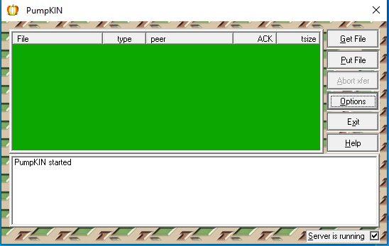
Once you have downloaded and installed PumpKin from the link above you will be presented with the below page:
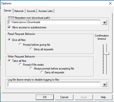
From here you will need to click on options which should bring up the following window:
On the above window you will need to set the TFTP filesystem root to the folder that you stored the firmware files in. In the example above I kept this in the Downloads folder but these can be stored anywhere you like.
You will also want to change the Read Request Behaviour to Give all files and the Write Request Behaviour to Take all files as shown in the screenshot above. Setting these options will allow the phone to request all the firmware files that it is looking for in the selected file path.
Once these have been set you can now click ‘OK‘ to save changes.
Step 3:
Putting your device into TFTP recovery mode. This may differ depending on what Yealink device you have so I have tried to cover them all in this guide for you.
T19, T2x, T3x, T4x, T5x
Step 1 – To recovery the above models you want to power off the device > press and hold the speakerphone button while powering on the device until you get to the following page:
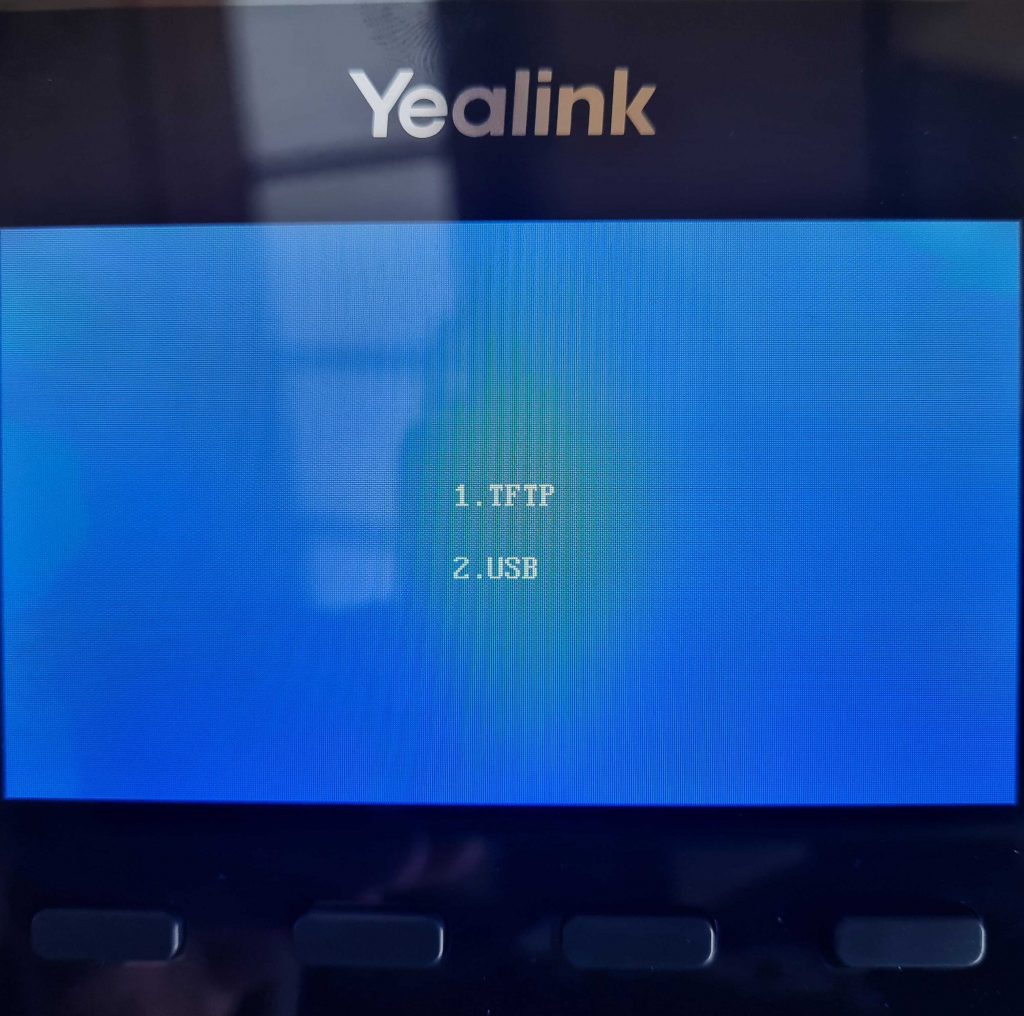
Unless your phone has a USB port in which case you will see these 2 options before the above:
If you are presented with this page first then click on 1. TFTP option.
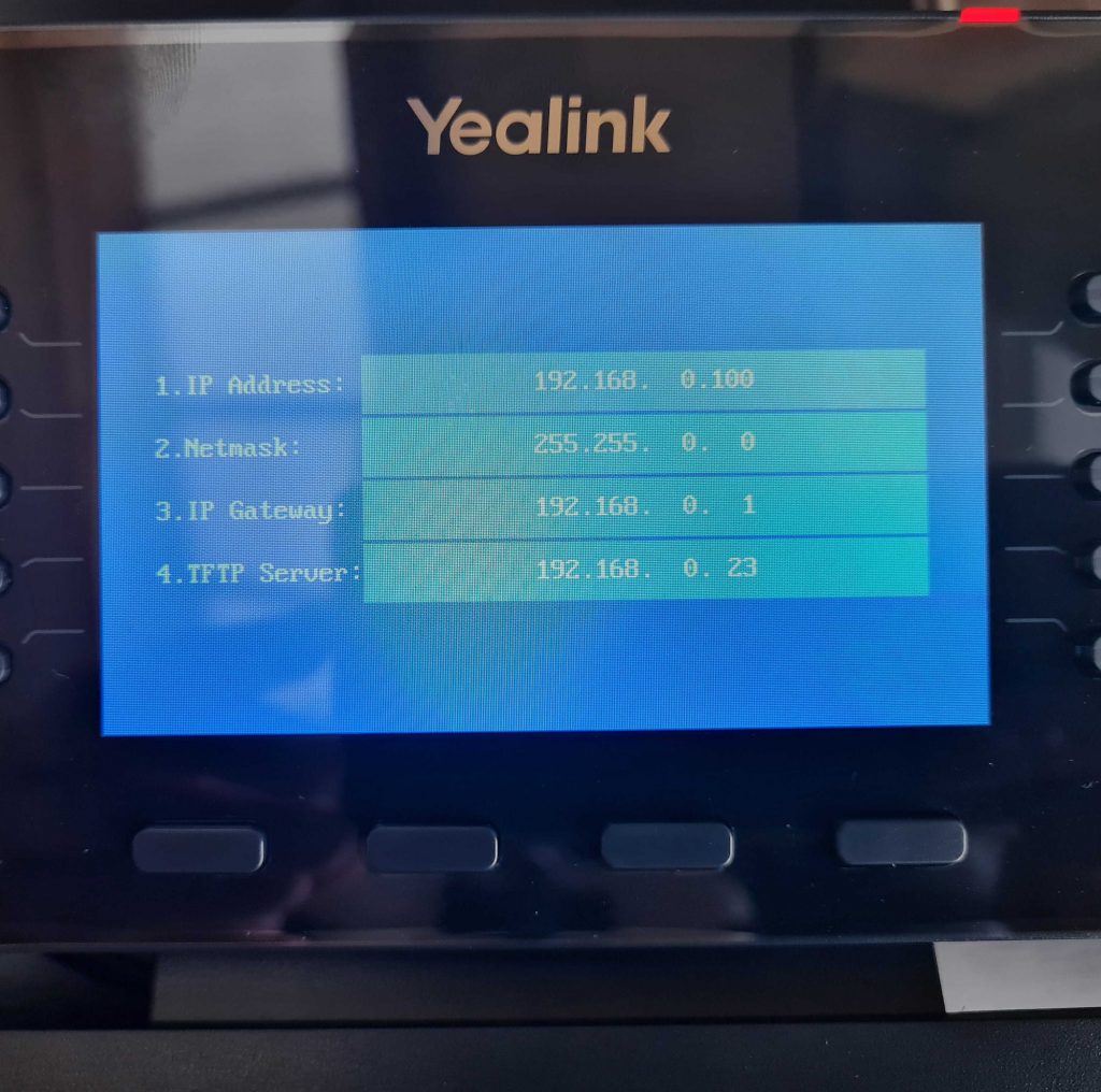
Step 2 – You should be on the page that has these four options:
IP address
Netmask
IP Gateway
TFTP Server
For these four options you will want to input the following:
IP address – Any unused IP address that is available on your network.
Netmask – For the netmask you will want to add the subnet mask of your network for example 255.255.255.0.
Gateway – This will be the IP address of your router.
TFTP Server– Finally this will be the IP address of the PC that is hosting PumpKin & Firmware files.
Once you have input these details press the ‘OK’ button on the handset, this will then start requesting the files that you downloaded and stored earlier.
Step 3 – Please note that this process can take a few minutes to complete. You should see Updating on the screen until eventually the phone reboots itself. If successful then once rebooted you should see the phones home screen as normal
If this was not successful then you should see a message such as Update failed, if that is the case then you will need to check your details and firmware file path and try again until successful.
W52P & W60B
Step 1 – To recover a DECT base station is a little different to a deskphone.
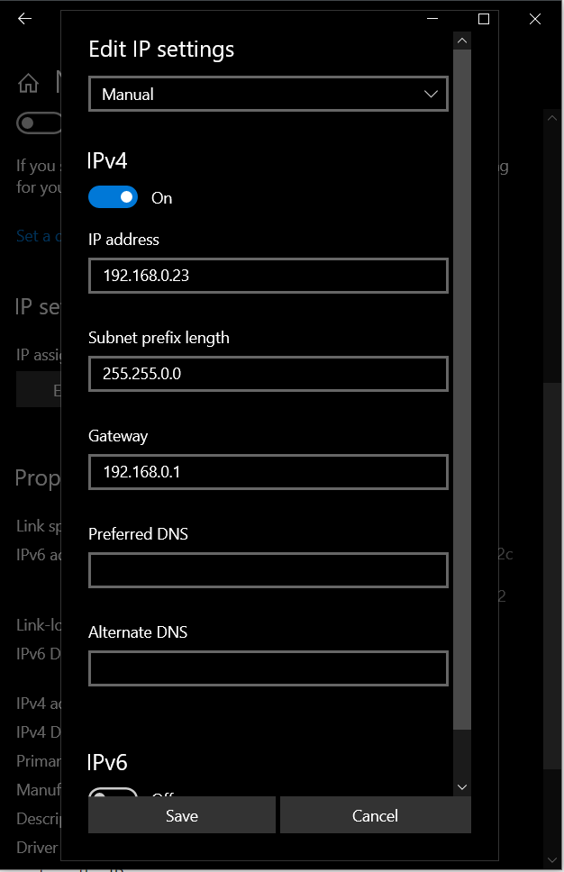
DECT equipment requests the files from a specific IP address so you will need to make sure that your PC that is hosting PumpKin is configured with the following information as per below:
Step 2 – During the recovery the base station should get an IP address of 192.168.0.100 and will request the firmware files from the IP address above (192.168.0.23)
To put the base station into recovery mode you will need to unplug the unit press and hold the paging button (only button on the base station) and power on the device while still holding the paging button until all the lights turn on one by one (Power, Network & Phone/Dect)
Step 3 – Just like the deskphone this will take a few minutes to complete. Once successfully complete the base should reboot and all lights on the base should be solid. The device should now get an IP address via DHCP and can now be accessible.
If you have any problems/issues with any of the above please contact support@provu.co.uk or call 01484 840048 option 2 for support.
The steps below will show you how to enable EHS both through the phones interface and the web interface on your Fanvil phone.
Phone Interface
Step 1:
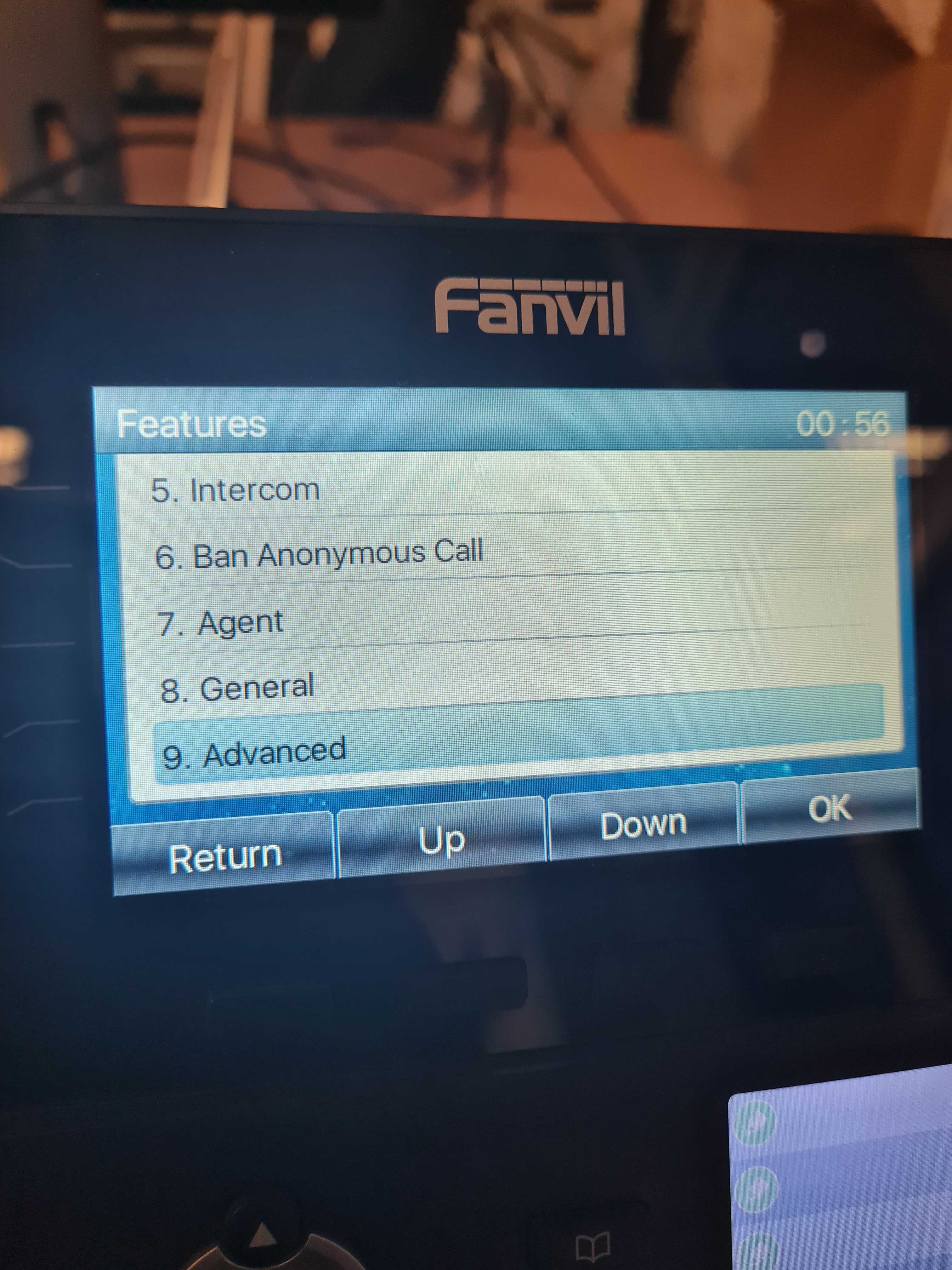
Go to Menu > Features > Advanced > EHS as shown below:
Step 2:
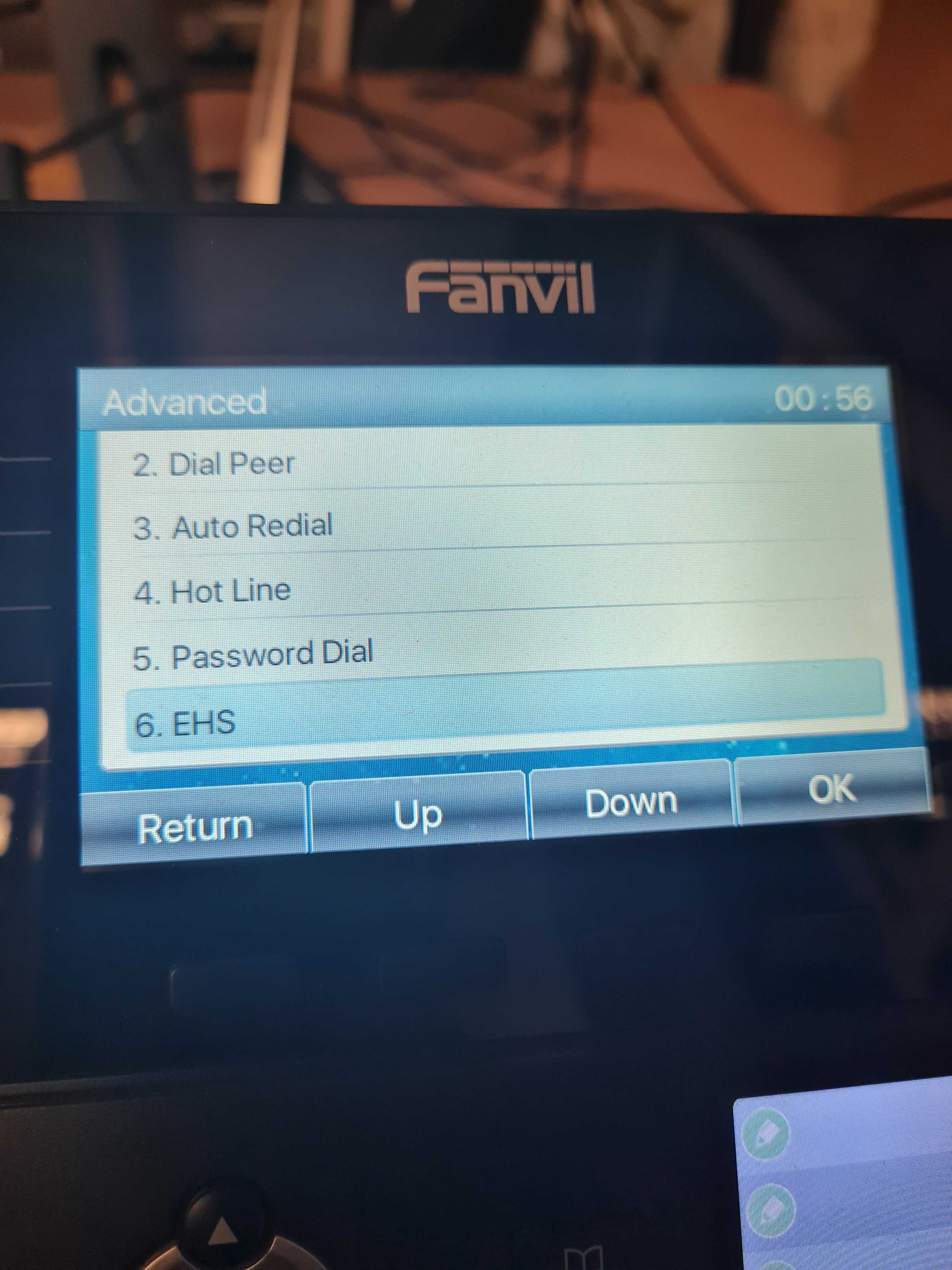
Using the right arrow key set the EHS option to ‘Enabled‘ and press ‘OK‘ to save changes:
Web Interface
Step 1:
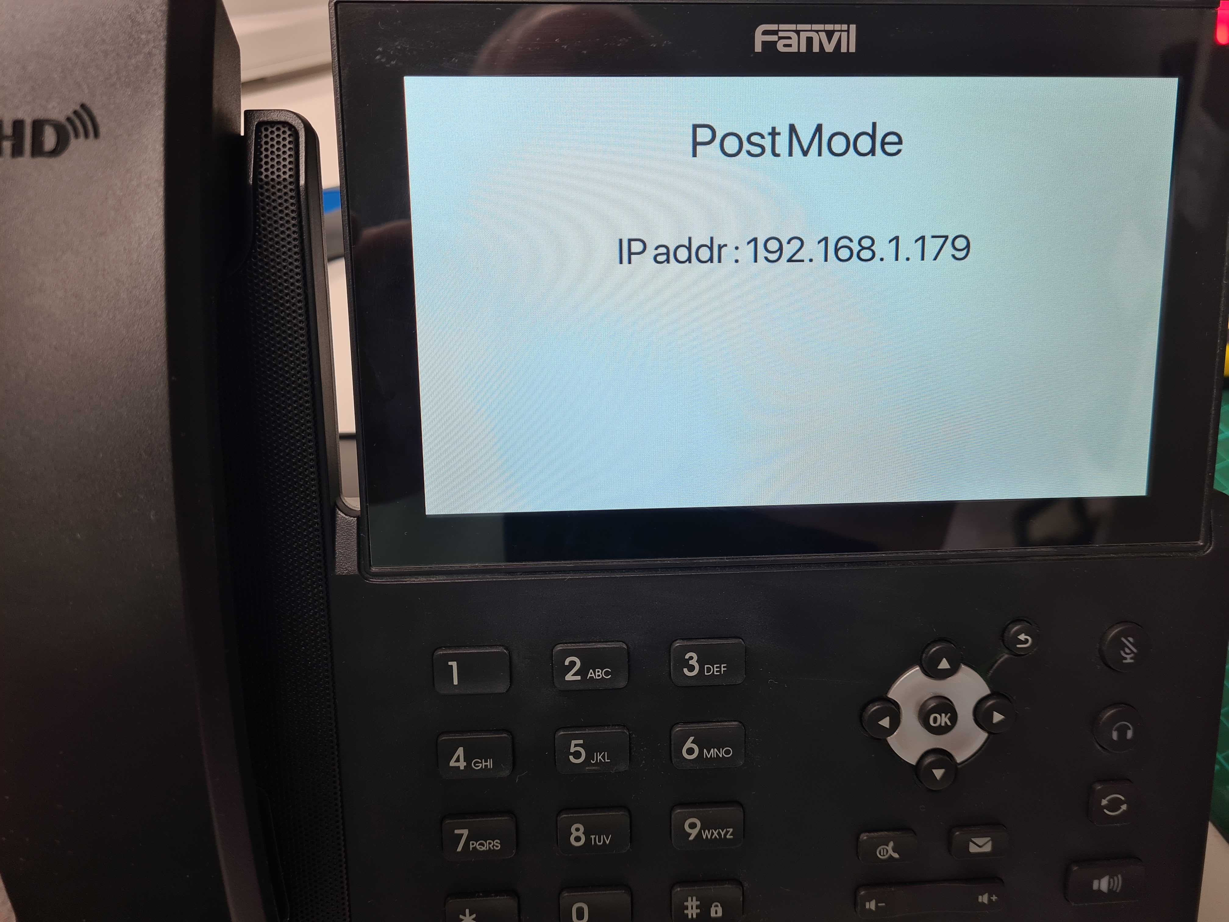
Find the IP address of your Fanvil phone by going to Menu Status or by pressing the ‘OK‘ button.
Step 2:
Once you have obtained the IP address enter this into your web browser you should be then prompted for login credentials, by default these are:
Username = admin
Password = admin
Step 3:
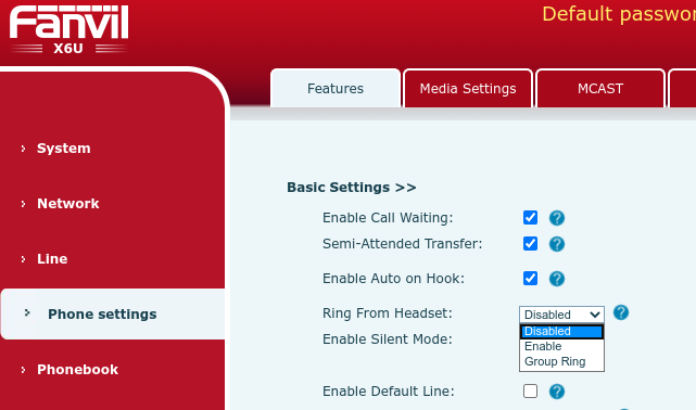
Once successfully logged into the web interface navigate to Phone SettingsFeatures > under Basic settingsEnable a setting called ‘Ring From Headset‘ as shown below:
Step 4:
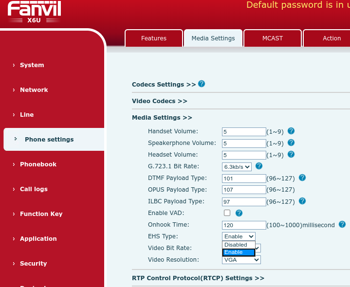
Now go to Media Settings > EHS Type > Enable > finally click Apply.
You should now be able to answer and end calls using your wireless headset.
If you have any problems/issues please contact support@provu.co.uk or call 01484 840048 option 2 for support.
You may be getting reports from your customers saying that when they are on a call, the opposite party is telling them that their audio is too quiet, or maybe even too loud when they talk. Usually this isn’t a problem because the opposite party can adjust the volume of the person calling with their own phone, but what if the opposite party has already done that and it’s still too quiet or too loud?
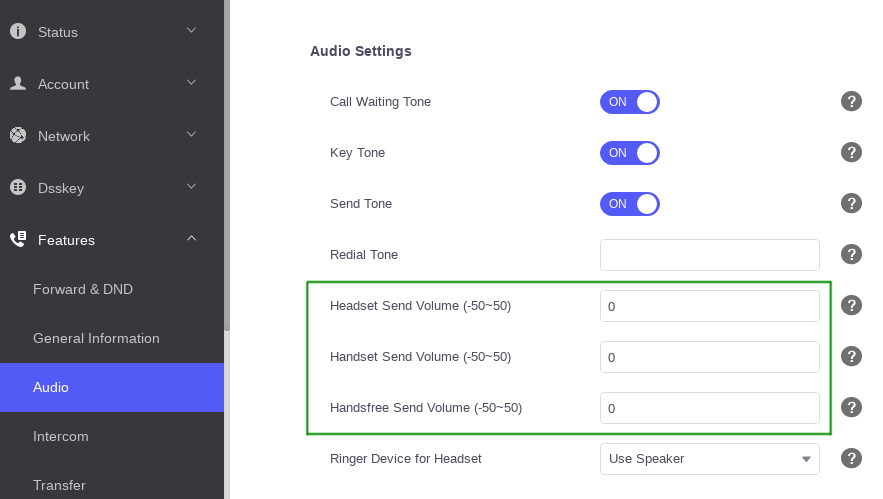
If that is the case then you may be able to adjust three settings on the Yealink device. These can found on the web user interface by going to the ‘Features’ > ‘Audio’ page and adjusting the settings in the image below outlined in green.
An alternative way to think what these settings do is adjusting how sensitive the microphone is on the device. You can adjust the handset, headset and handsfree sensitivity to be weaker or stronger. The valid values are between -50 and 50. The higher the value, the louder it should be. The lower the value, the quieter it should be.
When adjusting this setting it is important to be cautious. Incorrectly configuring the value can have adverse effects on the audio quality so it’s advisable to gradually increase or decrease the value until you find the right spot.
If you control your own provisioning server and would like to configure this remotely you can use the provisioning parameters below: