It is still possible to access the old-style web user interface of the D862 and D865 by navigating to the IP address of your phone with “http” and port “3112”:
Example: http://192.168.1.15:3112
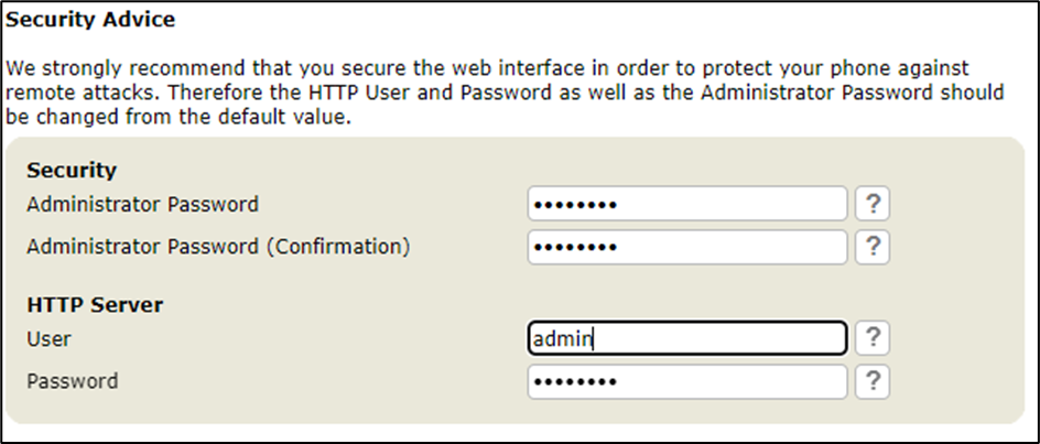
Securing the old-style interface
Once you have accessed the old-style web user interface, it will display security advice where you can setup a HTTP user, HTTP Password and an administrator password to secure your device. If you accidentally navigate away from this page, you can go to ‘Advanced > QoS/Security’ and configure these settings from there:
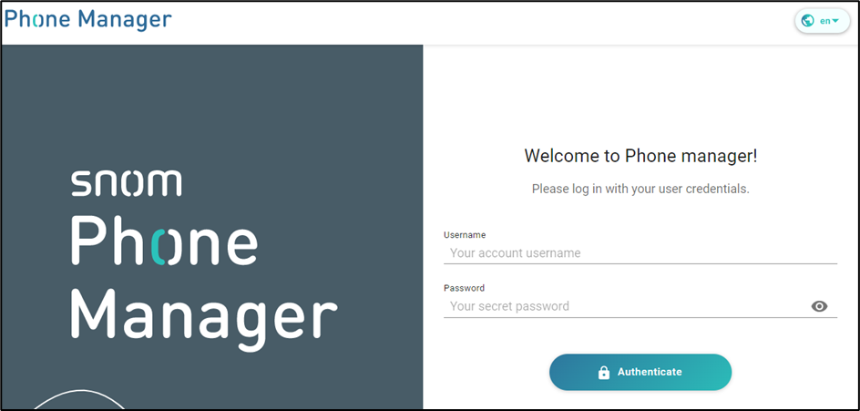
How to login to the new web user interface and secure it.
You’ve received your new Snom phone, you’ve plugged it into the network, it has obtained its IP address. You enter this into your web browser and you are presented with this login page. There’s no default username or passwords here so go ahead and click the ‘Authenticate’ button to login.
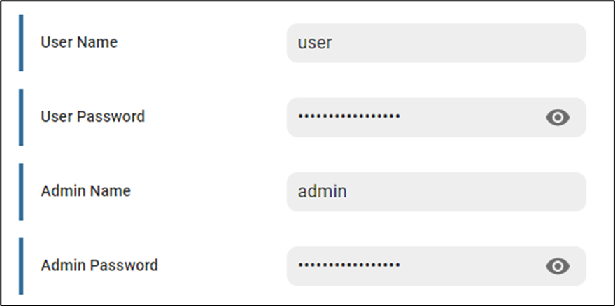
Once logged in, you will see some warnings saying a password has not been set for the ‘admin’ and ‘user’ account. To configure these, go to ‘Security > Advanced’ and populate the fields below and click ‘Apply’.
New provisioning parameters for a new interface
Due to the Snom D862 and D865 having a new web user interface to manage the devices, there are also new provisioning parameters to secure them.
Turning off admin mode will restrict unauthorised access to admin settings such as performing a factory reset, changing SIP credentials etc.
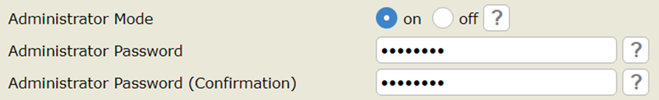
Web user interface method
To turn admin mode ‘off’ via the web user interface go to ‘Advanced > QoS/Security’ and set “Administrator mode” to ‘off’ and click ‘save’. – Default pin is ‘0000’ but ensure this is changed to secure your phone even further.
Phone user interface method
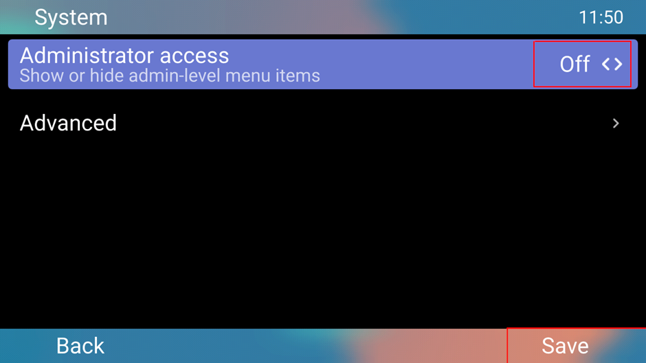
You can turn ‘admin’ mode off on the phone user interface by accessing the following:
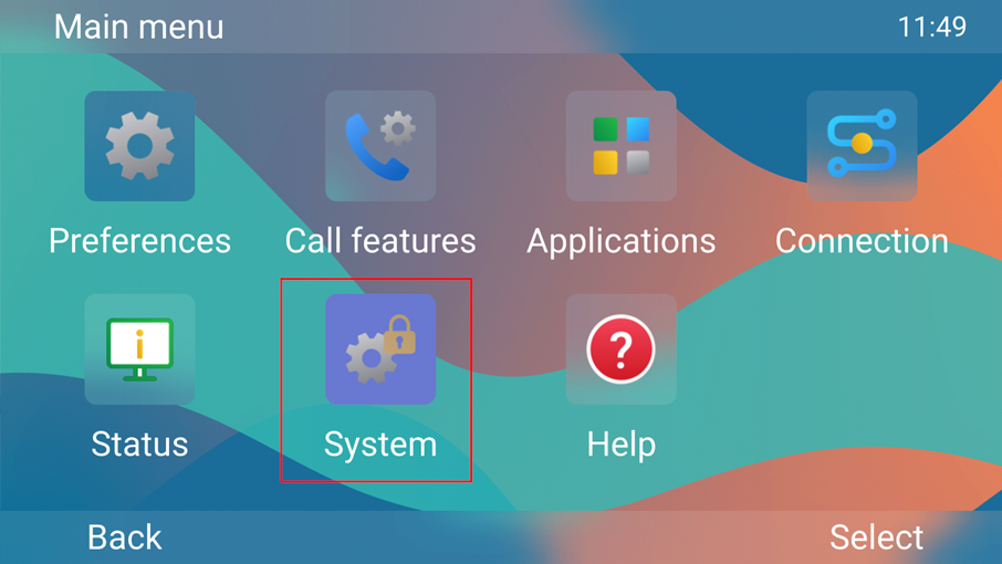
‘Menu > System > Administrator Access = Off > Save’
I hope this blog helps you to get started with your new devices. If you need any further support with the new Snom D8xx series, please contact us on: 01484 840048, our support team will be happy to help you with any queries you may have.
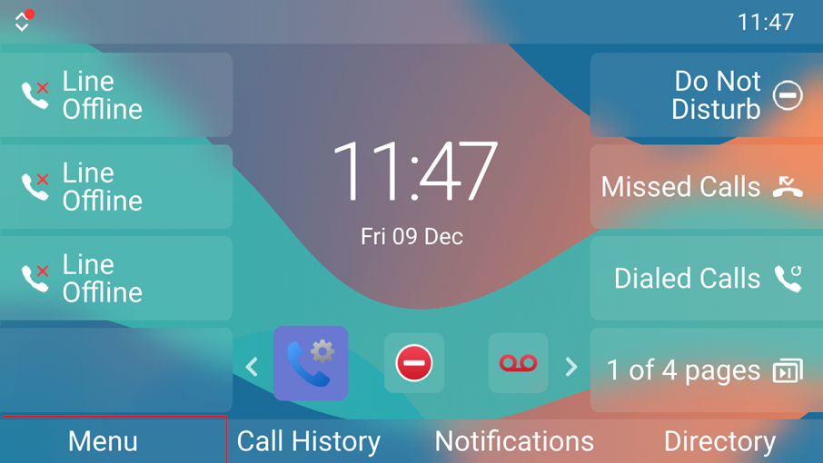
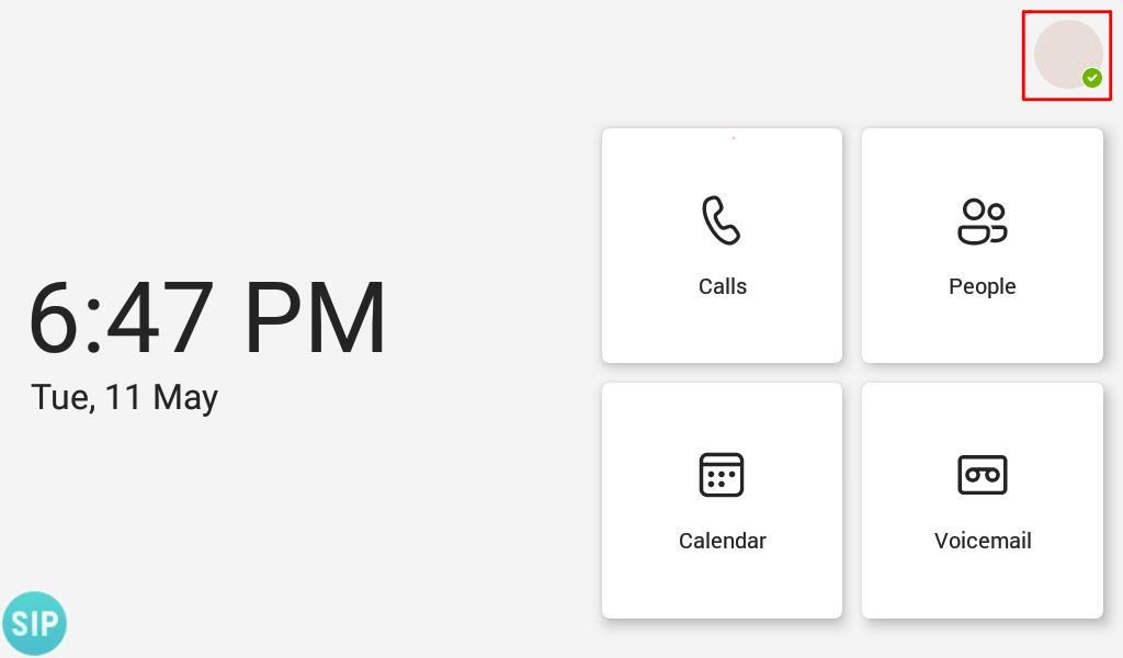
If desired on your Yealink Teams phone you can set a screen lock to prevent unauthorized people from making changes to your device, scheduled meetings or prevent them from making outbound calls. When the screen is locked you can still answer incoming calls.
Step 1 – Press your account icon in the top right hand corner where it shows your account’s presence status
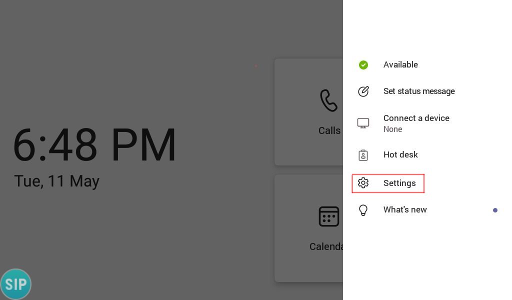
Step 2 – Select ‘Settings’
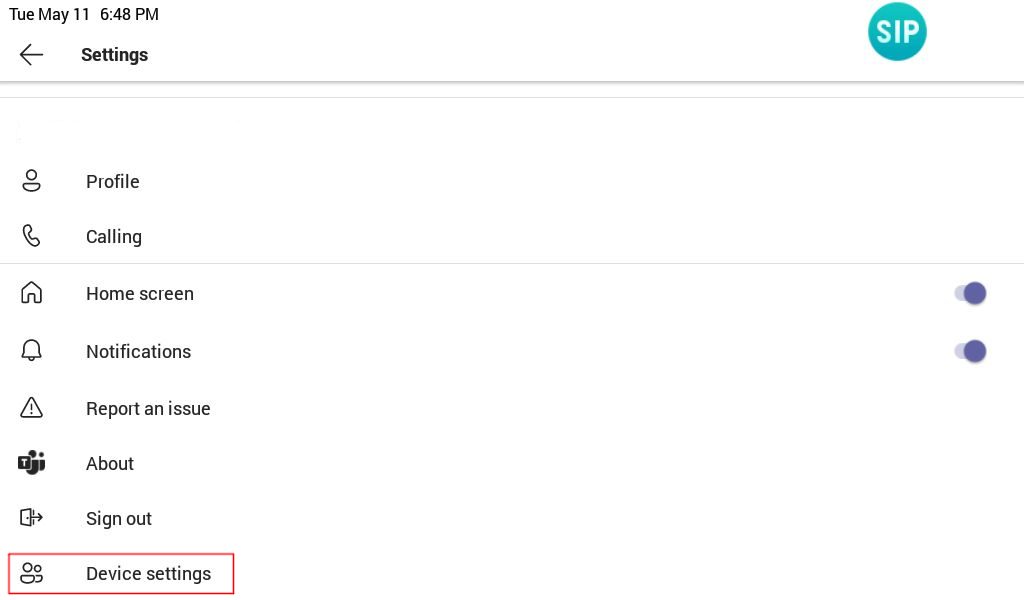
Step 3 – On the settings page scroll down and select ‘Device Settings’
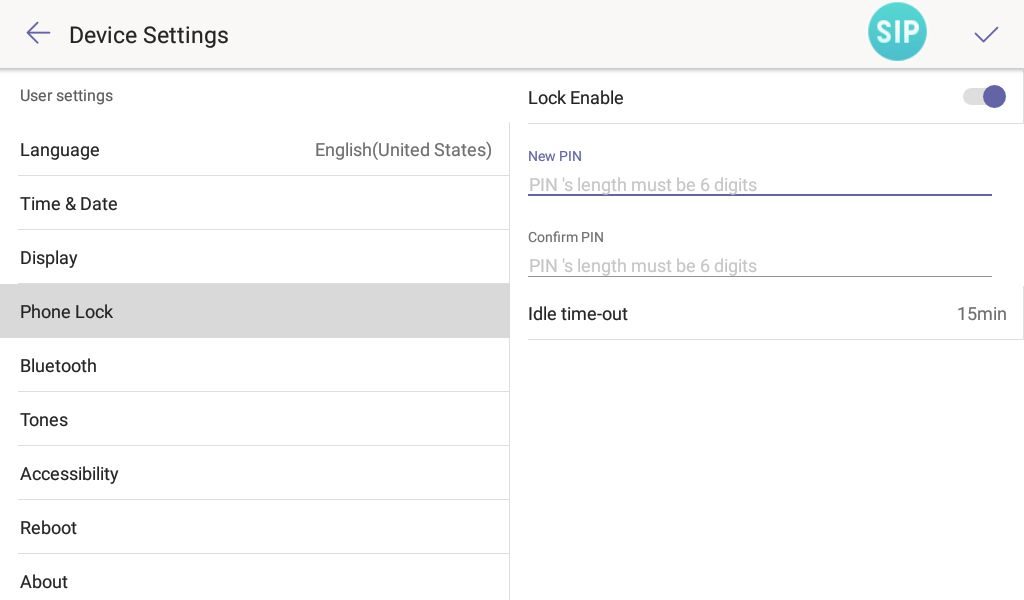
Step 4 – On the ‘device settings’ page find ‘Phone Lock’ and move ‘Lock Enable’ to the ‘ON’ position. Once you have done that enter a PIN with the minimum length of 6 digits, and then enter the digits again to confirm them. You may also wish to decrease the idle time-out to something less that 15 minutes as there’s no way to manually lock the device.
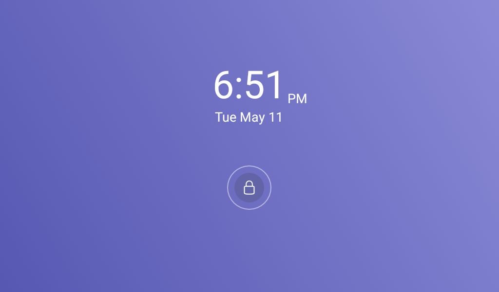
Step 5 – When your phone screen locks it should change to the one shown in the image below, press the padlock icon and enter your pin to unlock to the device.
If you would like to disable screen lock, go to ‘Settings’ > ‘Device Settings’ and change ‘Phone Lock’ to disabled. If your device is forcibly being set with a screen lock you must speak to your system administrator about getting it disabled.
If you have purchased your Yealink Team’s devices from ProVu and you are having difficulty with this blog post, or anything else related to your device please send an email to support@provu.co.uk explaining your issue.
The following blog post was done with a T56A running firmware version 58.15.0.124. The same steps should apply to the following models on the latest firmware version: T55A, T56A, T58A, CP960, MP54, MP56, MP58
You can enable hybrid mode directly through the web user interface of the Teams device. This allows you to use a SIP account to make and receive calls, as well as using your Teams account.
Part 1 – Enable Hybrid mode
Step 1 – Access the web user interface of the phone by entering the IP address of the device in to a web browser. You need to specify ‘https’ and port ‘443’, (Example: https://192.168.1.15:443) in order for the login page to load otherwise you will see an error saying this site cannot be reached.
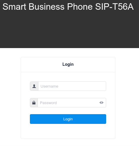
Step 2 – Once you are presented with the login page for the web user interface, login to the device. By default the credentials are ‘admin’ for the username and password.
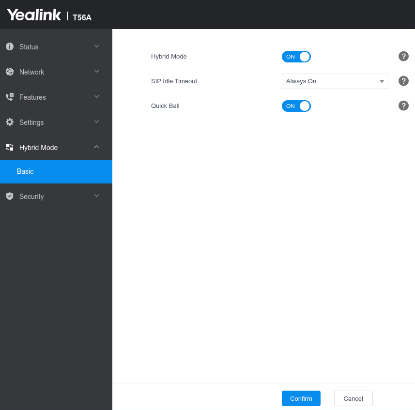
Step 3 – Select Hybrid mode down the column to the left and choose basic. When the page loads move the ‘Hybrid Mode’ slider to ‘ON’.
You will then be presented with two settings, SIP Idle timeout and Quick Ball. The SIP Idle timeout configures if the device should revert back to teams mode after a period of inactivity. The Quick Ball mode is a handy setting that when enabled presents a little button on the screen to flick between teams mode and Hybrid (SIP) mode.
Step 4 – Once you are happy with the settings picked click confirm and the phone will restart.
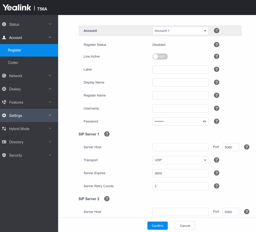
Step – 5 Once the phone has restarted login to the web user interface and click ‘Account’ to setup your SIP account on this device.
Note: If you have Quick Ball turned off, you will need to follow the steps below to access Hybrid mode from the phone user interface otherwise you can easily flick between the two modes via the Quick Ball.
Part 2 – Access SIP (Hybrid mode) from the Phone User Interface
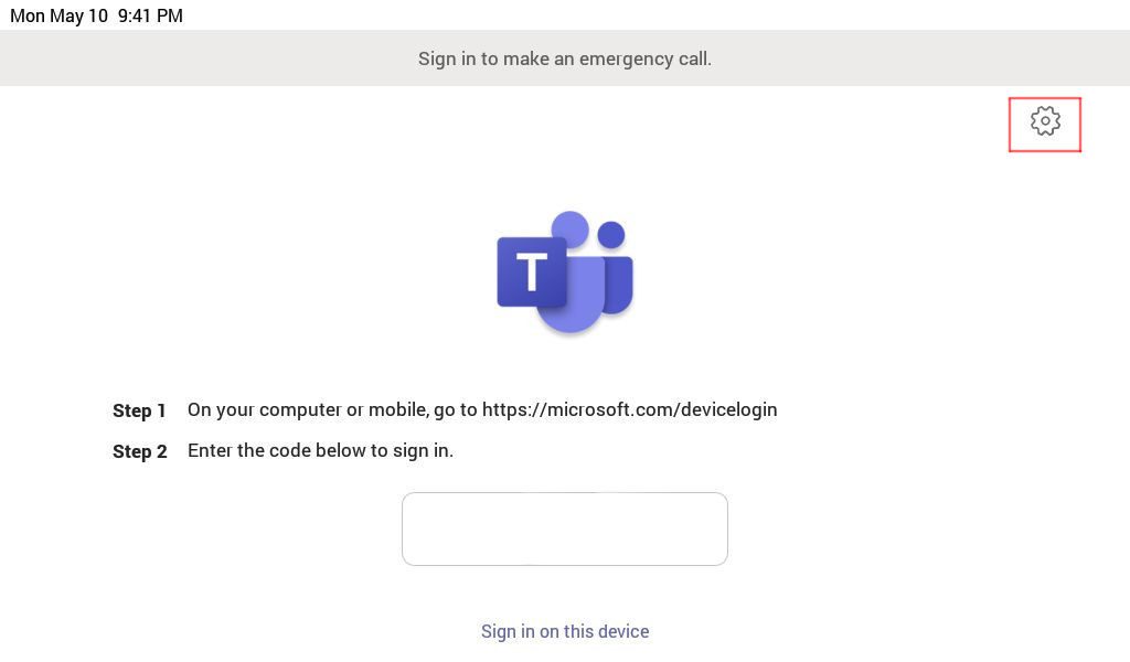
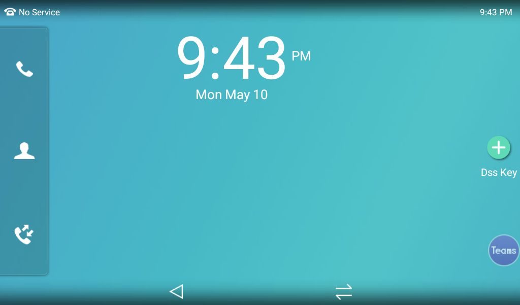
Step 1 – From the settings menu go to ‘device settings’, or when on the sign in screen click the cog symbol highlighted in the image below.
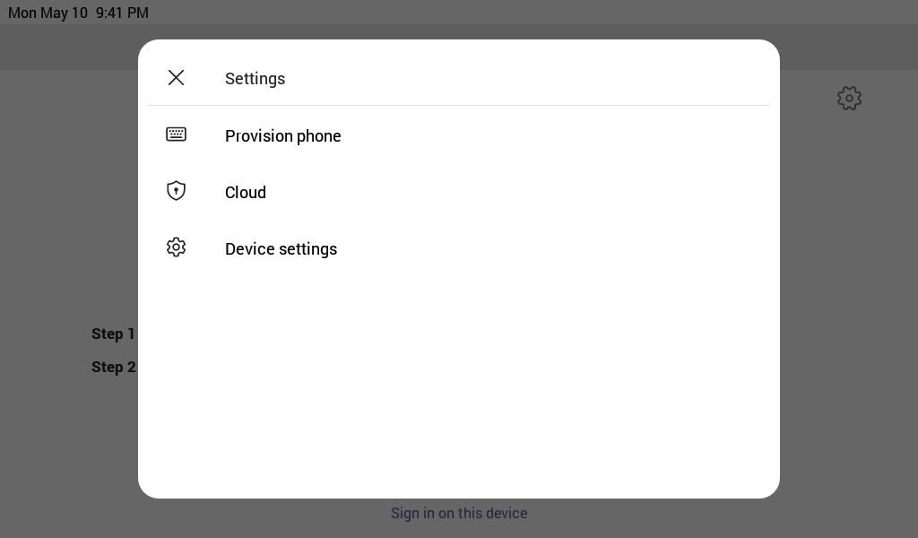
Step 2 – When the new page opens click ‘Device settings’
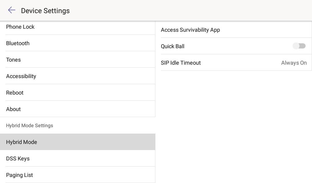
Step 3 – Once on the ‘device settings’ page scroll down to ‘Hybrid Mode’ and you should see the page as shown in the image below. To proceed to access ‘Hybrid mode’ click ‘Access Survivability App’
If you would like to quickly switch between your teams and SIP account I would recommend turning on the Quick Ball feature. This will allow you to change between Teams mode and Hybrid mode at the click of a button. The ‘SIP Idle timeout’ configures if the device should revert back to teams mode after a period of inactivity.
Step 4 – Once you have clicked Survivability you will see a similar screen to the one below and if you have an account registered you can start placing and receiving calls.
In the image below you can see a little circle in the bottom right corner saying teams. This is the Quick Ball to easily change modes, otherwise press the two lines at the bottom of the screen to go back to teams mode and follow the steps above to get back in to hybrid mode.
If you have purchased your Yealink Team’s devices from ProVu and you are having difficulty with this blog post, or anything else related to your device please send an email to support@provu.co.uk explaining your issue.
This blog post was created with a T56A on firmware version 58.15.0.124 but the process should be the same across all Teams desk phones. In order to login to a Yealink Teams device, you need a certain subscription as outlined in this blog post.
Method 1 – Using an internet capable device with a login code
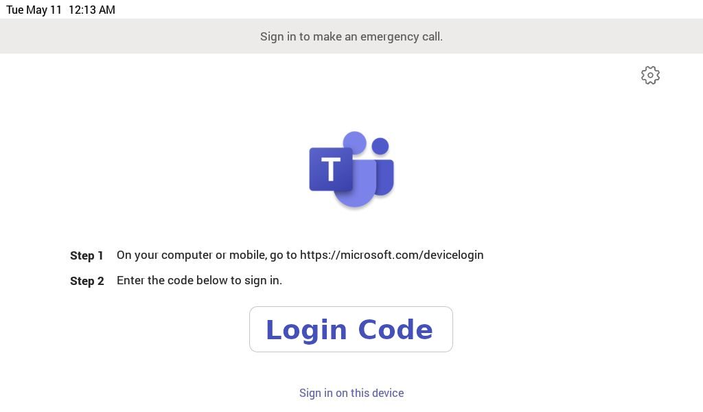
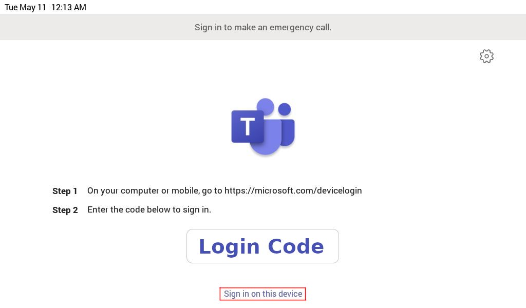
Step 1 – Follow the instructions on the login page of your Yealink Teams device, example shown in the image below, it tells you to web browse to the following URL on an internet capable device: https://microsoft.com/devicelogin
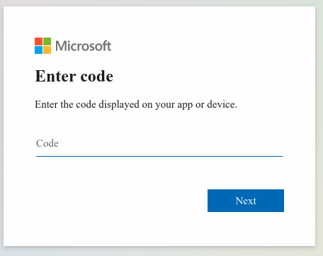
Step 2 – Once you’ve browsed to that URL enter your login code from your devices login screen.
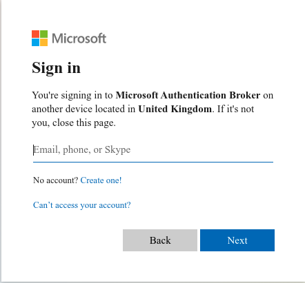
Step 3 – Once you’ve entered the code, you will be presented with a page to enter your email address.
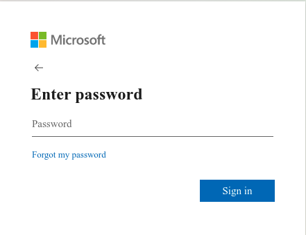
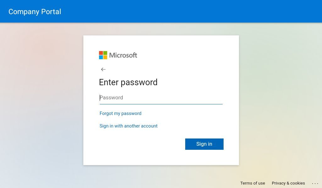
Step 4 – Once you’ve entered your email address, you will then be asked to enter your password for this account.
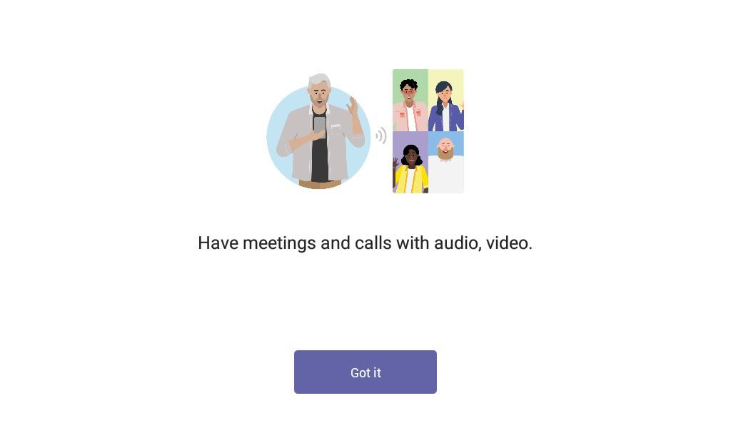
Step 5 – Once you have done that, your phone will automatically sign-in to your teams account and the web page will tell you to close the page. If your phone is nearby you may see it automatically start to log you in and then your phone will display this page. Click ‘Got it’ to start making or receiving calls.
Method 2 – Using the phones user interface
Step 1 – On the device’s login page, press “Sign in on this device”
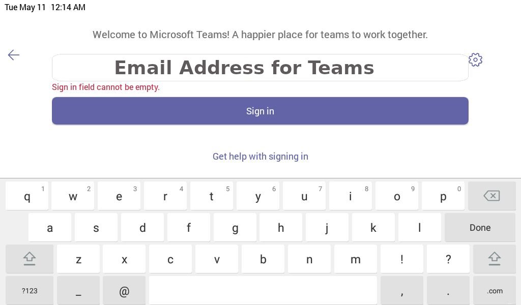
Step 2 – Once you have done that a new screen will load asking for your to enter your Microsoft Teams email address, Once you have done that click the sign in button.
Step 3 – Another screen will then load asking you to enter the password for the Microsoft Teams account you are trying to sign in with.
Step 4 – Once you have done that, it will cycle through some more screens and eventually, it will have signed in to your Teams account on this device. Click ‘Got it’ and you can start to make and receive calls.
If you have purchased your Yealink Team’s devices from ProVu and you are having difficulty with this blog post, or anything else related to your device please send an email to support@provu.co.uk explaining your issue.
At the time of writing, and to the best of our knowledge these are the requirements to be able to log in to a Yealink Teams device with a Microsoft Teams account.
You will need one of the following Microsoft subscriptions, but these do not allow PSTN calling. It’s only possible to communicate with other Teams users on your system. Please also note you can not login with a free to use Microsoft Teams account.
Supported Microsoft Teams Subscriptions:
Microsoft 365 Business Basic
Microsoft 365 Business Standard
Microsoft 365 Business Premium
Microsoft 365 E3 or A3
Office 365 E3 or A3
If you want to place PSTN calls you will also need an additional subscription to the Microsoft 365 Business Voice service (available for qualifying plans only) or have a Microsoft 365 E5 service.
Please be aware that Microsoft 365 and Office 365 are not the same.
Below are some links so you can compare the available services, but make sure to read the small print to fully understand which services are offered and which are excluded with the plan. If you are still unsure I’d recommend reaching out to Microsoft and explaining your interest and requirements.
Important: Additional Microsoft plans are required for the Yealink Microsoft Teams Rooms Systems. This page can be used to identify which plan you will need.
You may be getting reports from your customers saying that when they are on a call, the opposite party is telling them that their audio is too quiet, or maybe even too loud when they talk. Usually this isn’t a problem because the opposite party can adjust the volume of the person calling with their own phone, but what if the opposite party has already done that and it’s still too quiet or too loud?
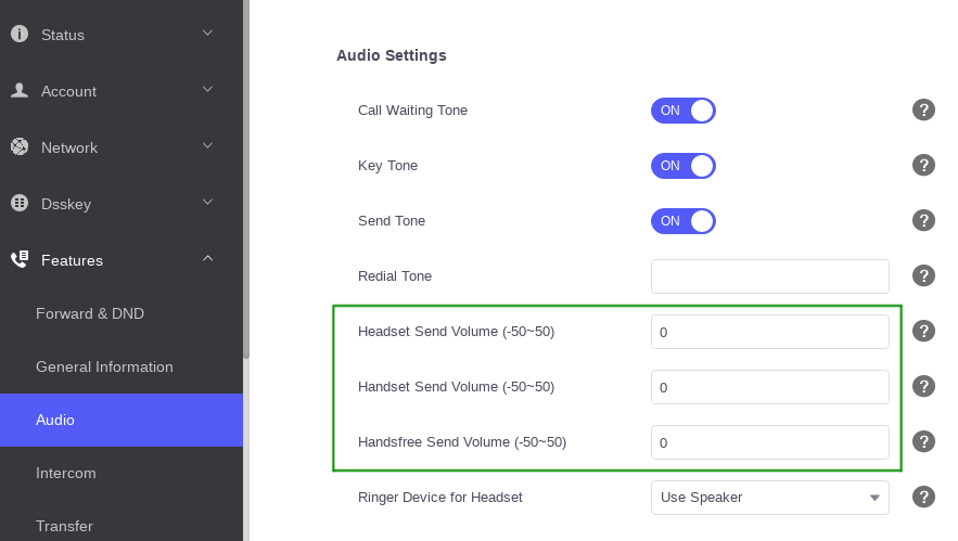
If that is the case then you may be able to adjust three settings on the Yealink device. These can found on the web user interface by going to the ‘Features’ > ‘Audio’ page and adjusting the settings in the image below outlined in green.
An alternative way to think what these settings do is adjusting how sensitive the microphone is on the device. You can adjust the handset, headset and handsfree sensitivity to be weaker or stronger. The valid values are between -50 and 50. The higher the value, the louder it should be. The lower the value, the quieter it should be.
When adjusting this setting it is important to be cautious. Incorrectly configuring the value can have adverse effects on the audio quality so it’s advisable to gradually increase or decrease the value until you find the right spot.
If you control your own provisioning server and would like to configure this remotely you can use the provisioning parameters below:
The aim of this blog post is to provide a guide on configuring the software side of the 2N IP intercom’s to be in a state where they can make and receive calls. It will also detail how to change the door release code and other switch related settings.
This blog post was created with a 2N IP intercom using firmware version ‘2.30.2.39.7’. Previous or future releases may vary slightly.
Prerequisite:
It is advisable to read and fully understand the installation manual for your intercom before proceeding with this guide. The installation manual can be found on the 2N wiki by selecting your model from the listed devices.
Step 1 – Obtaining the IP Address
By default 2N IP Intercom units obtain an IP address via DHCP. There are a few ways to obtain the IP address of 2N intercoms such as the DHCP table on the networks router, alternatively you can use the 2N network scanner, or by pressing certain calling buttons on the intercom just after bootup.
More information can be read about the network scanner, or button sequence on the following 2N FAQ page.
Step 2 – Accessing the web user interface
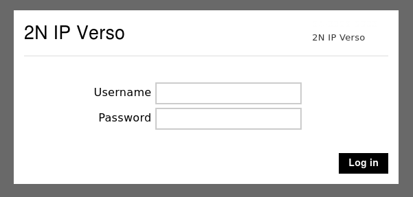
Once you have the IP address of the intercom open your web browser and type the IP address in to the top search bar. Once you press enter it should load the login page as shown in the image below.
The default username is ‘admin‘ and the password is ‘2n‘. If successful it will force you to change your password before proceeding.
Note: Some browsers work better than others, if you have issues with Chrome or Edge, try firefox. You may also see a certificate warning. This is expected behaviour and clicking advanced or proceed should take you to the login page above.
Step 3 – Checking & downloading the latest firmware version
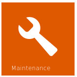
Once you have changed the admin password of the intercom it is advisable to make sure the unit is on the latest firmware version. You can do this easily by going to the ‘Maintenance’ section of the intercom.
To get to the maintenance section of the intercom you can use the ‘Maintenance’ button from the dashboard page
Dashboard Icon
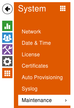
Alternatively click the ‘orange icon’ with 9 squares in it and choose ‘Maintenance’ from the list.
Sub-menu navigation
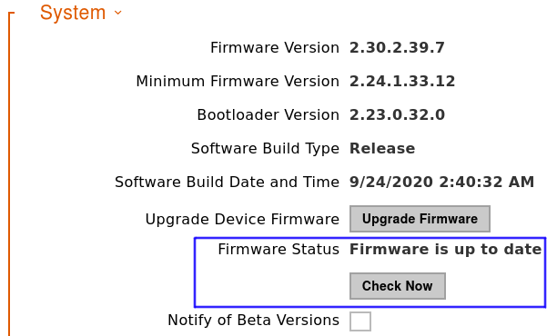
Once on the Maintenance page look for the ‘System‘ section shown in the image below. On this section it may already be reporting that there’s a new firmware version available next to ‘Firmware Status‘. If it doesn’t click the ‘Check Now‘ button.
If it reports a new firmware is available, read the ‘release notes’ carefully and if you are happy click proceed. The intercom will reboot during the upgrade. Once the upgrade is done this section should say the firmware is up to date.
Note: During the firmware upgrade do not remove the device from the network or interrupt the power to the intercom.
Step 4 – Configuring the SIP account & Call behaviour
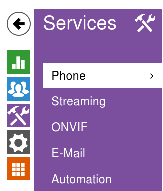
Now the intercom is on the latest firmware version we can proceed to configure the SIP account on to the device. This is done via the ‘Services‘ section and from within here the ‘phone‘ page as shown in the image below.
Sub-menu navigation
On the phone page it automatically takes you to the tab to configure ‘SIP Account 1‘ but the same applies if you are adding two SIP accounts.
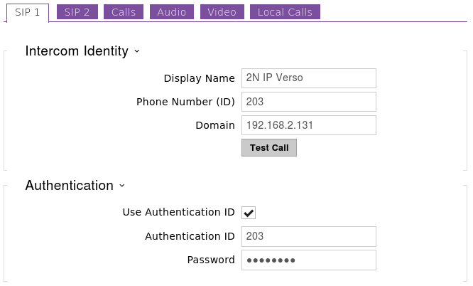
Hopefully you are familiar with applying SIP accounts to VoIP devices and the fields on this page already make sense. If they do, feel free to populate this page and get the SIP account Registered.
If you don’t have much experience and you have taken a hosted seat with an ITSP, and they have provided you with some account settings similar to the ones in the table below, you may not know where they need to go. The right column in the table shows where they would likely go on the 2N intercom.
Details from ITSP
Suggested 2N IP Intercom Fields
SIP Number/Account: 203
Phone Number (ID) field
SIP Password: Password
Password field
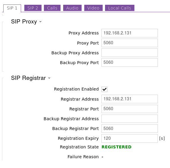
SIP Server: 192.168.2.131
Domain, Proxy address and Registrar field.
SIP Port: 5060
Proxy port & Registrar port
SIP Auth: WCXfg453SA
Authentication ID
Note: The SIP Server can be an IP address, but most likely it’s the ITSP domain name.
The SIP Auth is not always provided. If you didn’t get one sent the SIP Auth is usually the same as the SIP Number/Account.
The images below show an example intercom being configured with a SIP account and the Registration status going to REGISTERED. If your Registration status goes to failed and you are sure the details are correct send an email to support@provu.co.uk and we’ll be able to help.
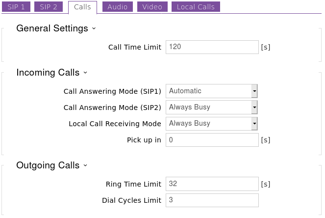
Now hopefully the SIP account is registered successfully with your ITSP or PBX. If it is we can continue with configuring the intercom’s call related settings.
You may want to configure the intercom to automatically answer incoming calls. This is useful for situations where someone maybe stood at the intercom and you want to talk to them without them having to press the calling button. Or this maybe beneficial if you was on a call with someone at the intercom and the call time limit was reached so the intercom disconnected the call.
This behaviour is achieved by changing ‘Call Answering Mode (SIP1)‘ to ‘Automatic‘. When set to ‘always busy‘ the intercom will always decline incoming calls.
Step 5 – Creating users for the Directory, a.k.a – Phonebook
The Directory is where we add users to the intercom and also configure unique/personal details for them such as an RFID keyfob or a Name and number which is what we are going to look at.
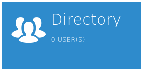
From the main dashboard click the icon below to get to the directory.
Dashboard Icon
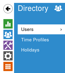
Or alternatively from the sub-menu navigation go to the section shown in the image below.
Sub-menu Navigation
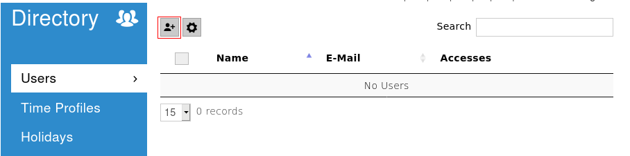
Once your on this page, to add a new user entry click the icon of a person as shown in the image below highlighted by the red box.
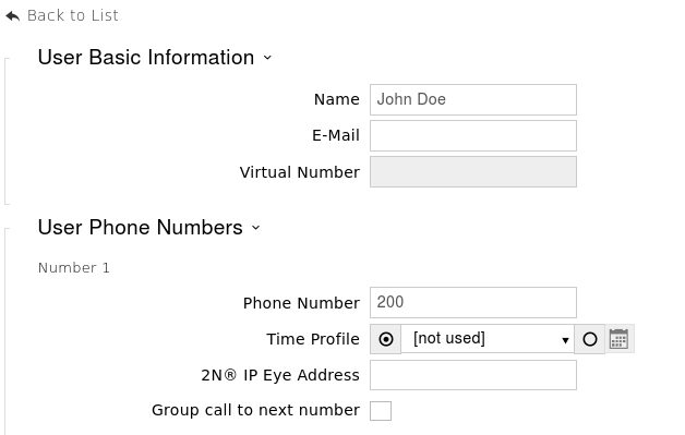
Once you click that button it will take you to a page asking for the Name, Email address, User phone numbers and user specific access settings. In this guide we’re just going to do the Name and Numbers. If this person has more than one number, add them in to the available number fields. If you want all three numbers to ring at the same time select the ‘group call to next number‘ and click ‘save‘ at the bottom of the page.
Example below:
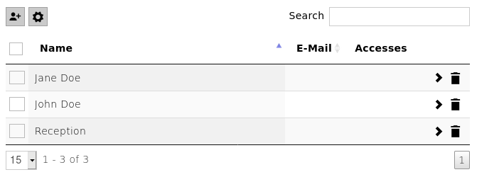
Repeat the above step for the desired amount of users. Once you’ve added some more users you should end up with a list when you go to the directory page.
Step 6 – Configuring the dialling buttons
This is the step where we program the calling button with the users to call. The system doesn’t automatically add the users because it may not be desirable to call every user.
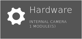
You can get to this section by pressing the Hardware icon on the dashboard.
Dashboard Icon
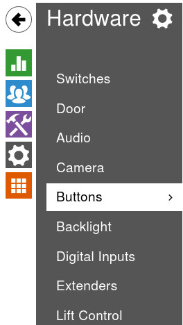
Or you can use the sub-menu navigation as shown in the image below:
Sub-menu Navigation
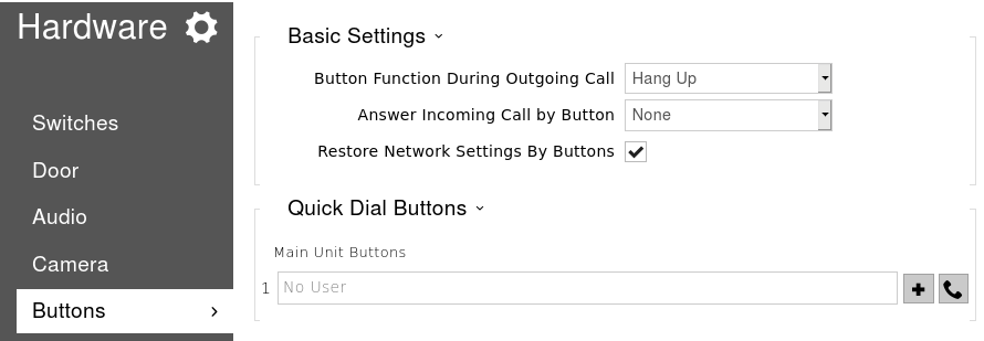
Once you are on the ‘Buttons’ page you will see that there are no users added to the main button. To add a user you need to click the ‘+‘ symbol next to the empty field.
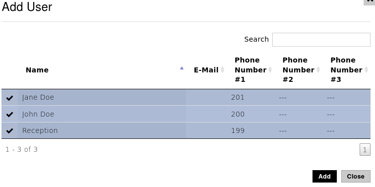
Once you click the ‘+‘ symbol it should bring up a new page with a list of the users from the directory, find the users you want to call, select them and click the add button. Example Image Below:
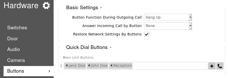
Once you’ve clicked add you should see the users appear against the main unit button. If you are happy with this click the ‘Save‘ button at the bottom of the page.
Now when the button on the intercom is pressed it should dial the programmed numbers via the SIP account configured in step 4.
A Handy tip, if the intercom isn’t nearby, to save yourself a walk you can click the ‘handset’ icon next to the assign user button to simulate a button press. (hopefully your near the phones to answer or hear them ringing).
Step 7 – Configuring the switch & activation code
The final step in this configuration guide is to edit the switch activation code and change some other settings that maybe relevant to your deployment. The default activation code is ’00*’ but it’s highly recommended to change this to something else.
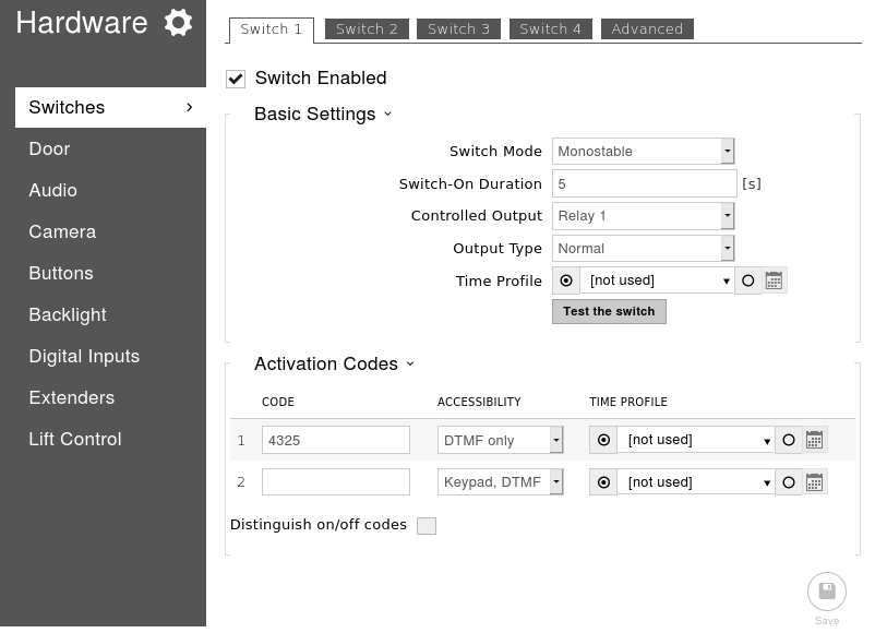
To do this we need to get to the ‘Switches‘ page and we can do this straight from the ‘Button’ page by clicking ‘Switches‘ at the top. Once on this page we can change the switch code under ‘Activation Codes‘.
As the image shows above you can apply two switch codes to each switch but usually one is enough. In the image above I have changed the switch code to 4325. Notice that I didn’t defined the ‘*’ which is be required when entering the code via DTMF (During a phone call).
If desired you can set it so the intercom doesn’t require the ‘*’ to be entered for confirmation by clicking the ‘Advanced’ tab at the top of the page and enabling legacy switch code.
Legacy switch code is only applicable for switch code 1.
Depending on your installation you may also need to change the settings in the table below:
Switch Setting
Description of Setting
Switch-on duration
Defines how long the switch will remain active in monostable mode. i.e – How long will the lock be released.
Controlled Output
Defines which output is used for this switch when activated.
If you’ve connected a lock to the ‘relay‘ on the PCB, select this.
If you’ve connected the lock to the ‘output‘ on the PCB use this.
Output Type
The type of lock being used will change which value needs to be applied.
‘Normal‘ is usually for a fail-secure lock, ‘Inverted‘ is usually for a fail-safe lock. ‘Security‘ is only applicable if the 2N security relay is being used.
To test your switch is working, you can click the ‘Test the switch‘ button on this page. If that works the setup is done. All you need to do now is make sure the intercom is working as expected.
Of course this is just a very basic guide covering the first steps on every intercom, if there are some additional requirements for the customer, or if your having issues with one of the stages above just send an email to: support@provu.co.uk
Also a very good place for 2N resources is the 2N Wiki and FAQ.
This blog post is going to show you how to configure a Polycom VVX device to capture the SIP traffic flowing between the device and SIP Server.
This can be useful to try and diagnose SIP registration, or outbound calling issues.
Step 1 – Accessing the web user interface
First we need to find the IP address of the Polycom device. This can be done by pressing the ‘Home‘ button (symbol of a house) on the phone and scrolling through the menu and selecting ‘Settings’ > ‘Status’ > ‘Network’ > ‘TCP/IP Parameters’ and on this page make a note of the values in the “IPv4 Addr” field.
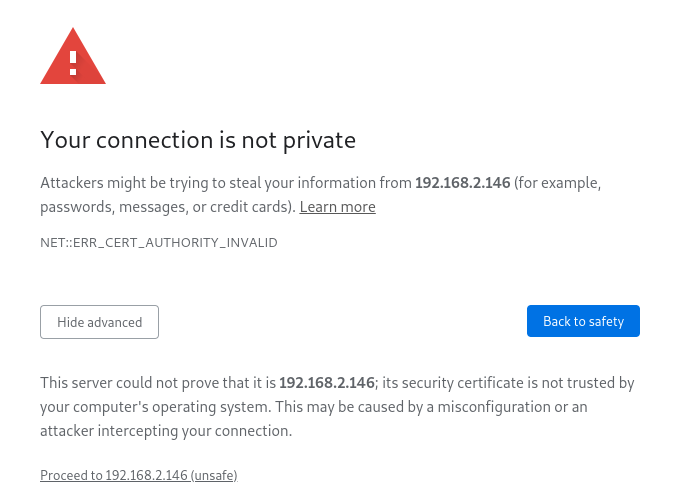
Now we have the IP address of the device, we need to access the web user interface. This can be done by launching a web browser and inputing the IP address in to the top search bar. You DO need to define ‘https://‘ and port ‘443‘ as the transport type and communication port as shown in the image below:
Once you have entered the IP address it may present a warning saying the connection is not private:
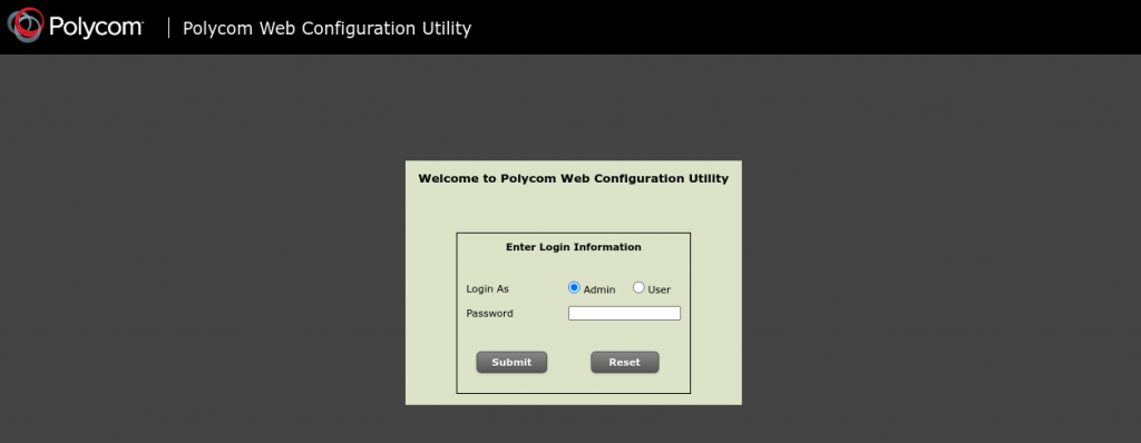
This is to be expected and you are seeing this because the TLS certificate on the device is not signed by a certificate authority recognised by the browser. Click the ‘Advanced’ button and then click “proceed to (‘IP Address’)”. Once you have done that you should be at the login page as shown in the image below.
To login, select the ‘Admin’ user and enter the password. By default this is ‘456’.
Step 2 – Configuring the log level
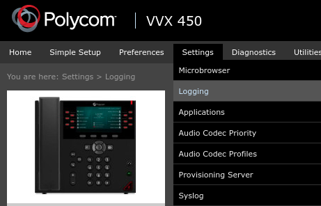
Once logged in go to ‘Settings‘ > ‘Logging‘
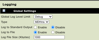
Once the ‘Logging’ page loads set the ‘Global Log Level Limit‘ to ‘Debug‘ and set the ‘Log File Size‘ to ‘1000‘ as shown in the image below.
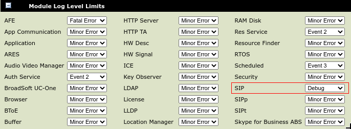
Next Expand the ‘Module Log Level Limits‘ section and change ‘SIP‘ to ‘Debug‘ as shown in the image below and click save at the bottom of the page.
Step 3 – Replicating the issue and downloading the log
Now the phone is configured to log the SIP packets flowing through the device it’s time to replicate the issue. If your issue is related to SIP Registrations a reboot of your device can be done to force a registration.
If your problem is with outbound calls not progressing you can go ahead and attempt to make a call.
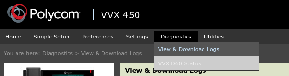
Once the fault has been replicated, login to the web user interface and this time go to ‘Diagnostics‘ > ‘View & Download logs‘
Once on this page you can view the logging information, but if a support engineer at ProVu has asked you to capture these files, please export all three file types by using the radial button below to change which file is downloaded and then click the ‘Export’ button.
Important – Once you’ve exported the logs, be sure to go back to ‘Settings’ > ‘Logging’ and click the ‘Reset to ‘Default’ button at the bottom of the page to revert the changes we’ve made.
This blog post is going to outline the steps to take to source the required file. If you contact the ProVu support team experiencing Registration or Call issues with the Cisco CP series of phones, we will require a PCAP trace capturing the problem to help identify the cause of the issue.
Step 1 – Access the web user interface
In order to access the web user interface of your device you will need to find the IP address. There are a few ways this can be done such as logging in to your router and checking the DHCP table, but most likely the easiest method and the one this blog post is going to cover is to get it physically from the phone.
You’ll need to press the ‘Settings‘ button on the phone which has the symbol of a cog. Once you have pressed this button scroll through the options available and select ‘Status‘ > ‘Network Status‘ > ‘IPV4 Status‘ and make a note of the IP address.
Once you have the IP address, open a web browser and type the IP address in to the top search bar and press enter as displayed in the image below.
Once you have pressed enter it should take you to the ‘Info‘ page. On here you need to select the admin user and then advanced options by clicking the red outlined text in the image below.
(By default there is no admin password applied but if you have set one it will require this)
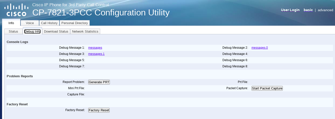
Once you have done that go to ‘Info‘ > ‘Debug Info‘ and you should be on the page below.
Step 2 – Capturing the ‘.pcap’ trace
On the ‘Info‘ > ‘Debug Info‘ page there is a section under ‘Problem Reports‘ that says “Packet Capture” with a button next to it. Follow the steps below to generate the file.
Press ‘Start Packet Capture‘ and select the capture filter to ‘All‘.
Replicate the issue – if your issue is related to outbound calls failing, attempt to place an outbound call. If your issue is related to Registration issues you can force a Registration by disabling and enabling the SIP Account:
To do this you need to go to ‘Voice’ > ‘Ext 1‘ and change ‘Line Enabled‘ to ‘No‘. Then click ‘Submit all Changes‘ at the bottom of the page. Wait 30 seconds for the web user interface to reload and then go back to ‘Voice‘ > ‘Ext 1‘ tab and change ‘Line Enable‘ to ‘Yes‘ and click ‘Submit all changes‘.
Press the button next to ‘Packet Capture‘ again (this time it should say “Stop Packet Capture“)
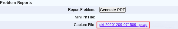
Once the trace has been stopped and generated you can download it from “Capture File” link outlined in the image below.
Once you have download the file please send it to the engineer requesting it, or to support@provu.co.uk if this is the first time reporting the issue.
When the CounterPath Bria Enterprise application is used on a mobile device the native operating system (Android or iOS) can close the application when it is running in the background to preserve battery life.
As this can happen, it is important to make sure the application is still receiving phone calls regardless of whether the application is open and running in the foreground, or if the application is:
Running in the background
Closed (Manually, or by the Operating System to save battery)
The Bria Enterprise Application ensures this by utilising the Bria Push Servers to take over the SIP registrations of the accounts. In most cases this is when the application is closed, or running in the background.
Now, because some SIP servers support multiple SIP Registrations per SIP extension and some only allow one SIP registration per extension it’s important to configure the CCS provisioning portal with the correct value to reflect your SIP servers registration method (otherwise your clients may end up missing calls).
The table below shows the setting that changes the application and Push servers behaviour. Hopefully from the information below you can choose the appropriate value. Remember after each change in the CCS portal each user needs to logout of their application and back in again to apply the changes.
Setting: accountN.briaPush.RegistrationMode (where N is a number from 1 to 5)
Parameters: 0,1,2,3
accountN.briaPush.RegistrationMode controls how the combination of the Bria Enterprise client and the Bria Push server interact with the SIP server. Continuous (2) and Standard (0) are used if your VoIP service provider supports multiple registrations. Single Device Takeover (3) and Single Device Emulation (1) are used if your VoIP service provider does not support multiple registrations.
0:Standard (Dual Instances Alternate): Allows both the Bria Push servers and the Bria Enterprise clients to register to a customer’s SIP account in an alternating manner. In this mode, there may be short overlaps of registration where both the Bria Push server and the Bria Enterprise client are registered to the SIP server. Some PBXs, SIP servers or SIP services may have issues with this registration overlap. If you encounter an issue with registering to the SIP server or receiving push notifications, select a different mode. This option is equivalent to the deprecated pushSingleRegistration setting set to False.
1: Single Device Emulation (Single Instance Alternate): Ensures that both the Bria Enterprise client and the Bria Push server unregister before the other one registers. In other words, the Bria Enterprise client and the Bria Push server never register to a PBX, SIP server, or SIP service at the same time. The Bria Enterprise client controls the registrations by requesting the Bria Push server to register only after the Bria Enterprise client has de-registered and alternately, by receiving confirmation that the Bria Push server has de-registered before the Bria Enterprise client registers directly to the SIP server.
The Bria Enterprise clients will also not register while they are in a call delivered through the Bria Push server so that they do not cause potential issues with the call in progress being terminated by the SIP Server. This option is equivalent to the deprecated pushSingleRegistration setting set to True.
Note that when in the Single Device Emulation mode, there are periods of time (typically fractions of a second) when neither the Bria Enterprise client or the Bria Push server will be registered to the PBX, SIP server or SIP service. This gap could lead to a missed call if the call is presented to the SIP server at the same time that neither element is actively registered. This is a downside of the requirement of the SIP server that only one element can be registered at any one time.
2: Continuous (App Foreground, Server Persistent): Ensures that the Bria Push server is always registered on behalf of the Bria Enterprise client. The Bria Enterprise client still registers directly to the SIP server when in the foreground, but the Bria Push server does not de-register from the SIP server. In this mode, all inbound calls and all outbound calls from the Bria Enterprise client are handled by the Bria Push server.
The Continuous mode, in particular, is used when a SIP server supports multiple registrations at the same time. This mode avoids any gap in SIP registration because the Bria Push server is always registered on behalf of the Bria Enterprise client. In the event of a call to the SIP account while the Bria Enterprise client is in the foreground, the Bria Enterprise client will receive an INVITE directly from the SIP server and via the Bria Push server. The Bria Enterprise client will filter out these duplicate events and only allow one of the call attempts to progress.
3: Single Device Takeover (Single Instance Takeover): This is an enhanced option of the Single Device Emulation mode. The Bria Enterprise client and the Bria Push server take over registrations from each other without unregistering first. Neither the Push server or the Bria Enterprise client sends SIP de-registration messages when transitioning from one element to the other. It aims to eliminate gaps that are present in the other registration mode. This mode is in some cases beneficial for SIP servers that only support single registration.