Browse Author

Chris Wright

Algo 8301 Multicast Line IN Audio

This guide is designed to show how to make an Algo 8301 multicast the audio it receives on the Line IN or AUX IN ports.

In this guide we will use two Algo 8301 units, the first as the Multicast sender and the second as the multicast receiver.

Configuring the Multicast Sender

Log in to the Algo 8301 Web GUI and change the following settings:

  • Basic Settings > Multicast
    • Multicast Mode = Master/Sender
    • Multicast Type = Regular (RTP)
    • Master Single Zone = Music
  • Additional Features > Input/Output
    • Audio Always On = Enabled
    • Audio Input Port = Aux IN or Line IN (depending on what port you are wiring your audio source to)

Configuring the Multicast Receiver

Log in to the second Algo 8301 Web GUI and change the following settings:

  • Basic Settings > Multicast
    • Multicast Mode = Slave/Receiver
    • Multicast Type = Regular (RTP
    • Basic Slave Zones = Tick “Music” box.

Thats It! Couldn’t be simpler. In my test, I chose the Audio Input Port as the Aux IN port, then connected my mobile phone using a normal AUX cable. I then connected some PC speakers to the Aux OUT port on the second Algo 8301.


When I played the music on my phone, it was played out over the speakers plugged in to the second Algo, which was receiving the audio over multicast.

This would be a great way to take an audio input source in one location, and broadcast the message across a large site with multiple speaker groups.

Direct IP Call Between 2N Helios IP and Gigaset N510IP

Here is a short guide on configuring direct IP calling between a 2N Helios IP intercom, and a Gigaset N510IP. The same process will work with a Gigaset N300IP.

Both units need to be plugged in, and connected to the same network. You need to connect to the web interface of each device to configure them.

Step 1: Configure the Intercom

Go to Services > Phone and edit the Domain setting. You need to set this to the IP of the intercom itself, in our example this is 192.168.2.64

path3416


Then you need to add an entry to the directory, to call the N510

path3381

Here I have used 200 but you can choose any number, you will need to use this number later when configuring the N510. The IP address part must be the IP address of the N510 unit, in our example this is 192.168.2.38

Step 2: Configure the N510

Go to Settings > Telephony > Connections and Edit one of the Connections.

N510-Connection

Here you add the number that you chose earlier, and the IP address of the 2N intercom in the 3 boxes shown – Domain, Proxy Server and Registration Server. You do not need to enter a password as the N510 does not actually register to the 2N intercom.

Settings > Telephony > Advanced VoIP settings.

N510-SIP-Port

Here you set Use random ports for SIP to ‘No’, and set the SIP port to 5060.

Finally, you need to go to Settings > Telephony > Number Assignment and make sure that your handsets are set to accept incoming calls from the account/connection that you just created.

You should now be able to call to the Gigaset by pressing the button on the front of your intercom. If you are still having problems, please contact our technical support team.

2N Wiring Diagrams

As we continue to sell more and more 2N Door Intercoms, we have had an increase in support calls from customers enquiring about the wiring aspect of these products.

To help with this, we have created wiring diagrams for some of the most popular setups that we have encountered, these can be found on our website:

Wiring Diagrams

Of course, we would always recommend hiring a qualified electrician to wire these units up, as doing so incorrectly could damage them or even stop them working completely.

If you have any questions about these wiring diagrams, or the 2N range in general, please contact our support team

Factory Reset RTX4002 Repeater

Below are some instructions on how to factory reset and RTX4002 repeater:

1. Power off RTX Repeater

2. Power on the RTX Repeater for between 1-5 secs (ie 2 secs) then power off

3. Power on RTX Repeater for between 25-35 secs (ie 30 secs) then power off

Now the RTX Repeater should be reset, power it back on and the light should be blinking slowly.

For more information on pairing the RTX with a Gigaset base station, please see our guide

Mitel 6865i and Plantronics EHS Headset

The following guide shows how to connect a Plantronics CS520 (This will also apply to the other headsets in the CS500 series) headset to the Mitel 6865i desk phone to allow EHS functionality (the making and hanging up of calls via the headset button).

As well as the CS520 headset and the 6865i phone you will also need a Plantronics APS-11 EHS Cable.

1) Connect the APS-11 cable to the back of the CS520 stand, using the end of the cable that has both an RJ45 connector and a 3.5mm jack connector. Both connectors should be plugged in to the respective ports on the back of the stand.

2) Plug the other end of the APS-11 cable into the RJ45 socket on the back of the Mitel phone, you will need to remove the plastic spacer clip from the socket on the phone in order for it to fit. Please refer to the user manual for help with this.

3) Finally, you need to change some settings on the Mitel phone to enable the EHS functionality. Make the following changes via the menu on the handset itself (press the button with the gear icon to open the menu):

i) Go to Preferences – Set Audio – Audio Mode. Select Headset from the list and press the tick button to confirm.

ii) Go to Preferences – Set Audio – DHSG. Select the “DHSG is On” option and press the tick button to confirm.

That’s it! The headset should now be able to make and receive calls using the EHS functionality.

If you have purchased these products from Provu, and can not get this to work, please contact our support team at support@provu.co.uk and we will be happy to help!

How to: 2N Video on Snom Screen

The 2N door intercoms have built in XML that allows you to stream the video feed from the camera directly onto the screen of a snom phone (760, 821, 870 models only).
This works by getting a static JPEG image and refreshing it frequently to make it appear as a video.

The URL you need to use is:

http://ip.addr.of.2n:80/enu/snom-video.xml

** Make sure to edit the URL so that it actually contains your 2N units IP address **

Now you need to browse to the web UI of your snom phone and add your 2N intercom to the directory. In the number field, enter the extension number of the 2N (the unit it presents as its Caller ID). Then in the Action URL field enter the URL shown above. Click the Add button to add the directory entry.

Now when you receive a call from your door intercom, the video stream will be shown on the display of your snom phone.

Please note, we recommend that you have the following firmware versions on each unit as a minimum:

Snom: 8.7.3.25
2N: 2.10

If you have any problems getting this to work, please email us at support@provu.co.uk.

How to: Resolve Snom Meeting Point DTMF Issue

We have reports of issues with DTMF tones on a snom Meeting Point, particularly when (but not limited to) dialling in to hosted conference facilities.

The user types the access code or conference PIN in correctly, but they are advised that the code is incorrect.
This is because the microphone on the Snom Meeting Point is picking up the DTMF that is played back when the user types a digit. The phone then sends this code twice (once from the actual key press using RFC2833 and once from the microphone using inband DTMF).

There are a couple of settings you can change on the Meeting Point to stop this happening depending on your users preference:
Please Note: The Meeting Point must be on firmware 8.7.3.25 or newer or the settings will not be present in the device

1) DTMF Volume:

http://wiki.snom.com/Settings/dtmf_volume

Reducing this to a lower setting (1 or 2) may be enough, but setting it 0 will stop the playback of the DTMF tones. This may not be desirable if the customer wants to hear the DTMF being played back to them so they know the key press has definitely registered.

2) DTMF Microphone Delay:

http://wiki.snom.com/Settings/dtmf_micro_delay

This setting temporarily disables the microphone when a DTMF key is pressed, to stop it from picking up the tone being played back through the speaker. Set this to 1000 so that it delays for 1 second (it is off by default).

The settings do not appear in the web interface so you will need to use the dummy setting URL to save these changes. Simply type either of the following URLs into the web browser on your PC (that is connected to the same network as the Snom):

http://ip.addr.of.snom/dummy.htm?settings=save&dtmf_volume=0

http://ip.addr.of.snom/dummy.htm?settings=save&dtmf_micro_delay=1000

You need to change ‘ip.addr.of.snom’ to the actual local IP of the Snom Meeting point.

Thats it! Your Meeting Point should now connect to hosted conference rooms without issue.
If you have followed the steps above and are still having issues please email support@provu.co.uk.

Configuring Gigaset Hybird PBX with Sangoma Vega 50 FXO Gateway

This guide is intended to show how to route calls to your Vega 50 4FXO Gateway and out over your PSTN Line. It also includes the settings to route inbound calls from the PSTN line to phones registered to the Gigaset Hybird PBX.

This guide assumes that you have already connected the Gigaset PBX and Vega Gateway to your network and have access to the web interface of each device. If your units are not already plugged in with access to the web interface, please consult the relevant product manuals to get to this stage.

This guide also assumes that you have registered one or more SIP phones to the PBX and configured them as Users on the system. If you have not already done so please consult the Hybird manual for details.

Configuring the Vega 50 4FXO Gateway

To configure this unit, use the Quick Config wizard on the Vega Web Interface. The settings need to be changed as follows:
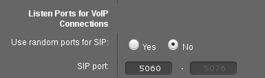
VoIP Tab

Registration Mode: Off
Outbound Proxy Used: No
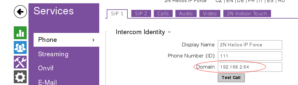
SIP Domain: IP Address of your Gigaset PBX
SIP Server IP/Name: IP Address of your Gigaset PBX

FXO Tab

These settings are applied for Interface 0201, assuming that you have connected your analogue line to the FXO1 port on the box.

Numeric Caller ID: Your Analogue Line Telephone Number
DID to Forward to SIP: Your Analogue Line Telephone Number

Once this has been done you need to click Submit, then Apply Changes and finally Save.
This is all the configuration that needs to be done on the Vega, we now need to configure the Hybird.

Configuring the Hybird

To configure this unit via the Web UI, follow the steps below:

Step 1

Go to the VoIP > Settings page and click New to add a new provider, configure the provider as follows:
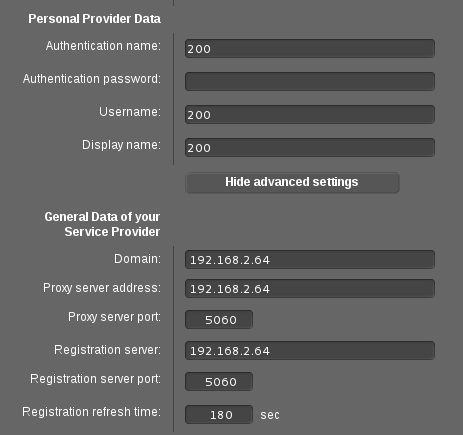
Description: Vega
Authentication ID: Your Analogue Line Telephone Number
Password: Leave this blank
User Name: Your Analogue Line Telephone Number
Domain: IP Address of the Vega Gateway
Registrar: IP Address of the Vega Gateway

Click Advanced Settings

Proxy: IP Address of the Vega Gateway
Provider Without Registration: Enabled

Click OK to save the setup.

Back on the VoIP > Settings page, click the Locations tab:

Set Default Behaviour: No Registration and click OK to save the setup

Step 2

Go to the Numbering > Trunk Settings page. You should see a Trunk called Vega with the External Port set to SIP Provider. If this is not there, please check that you have completed Step 1 successfully.

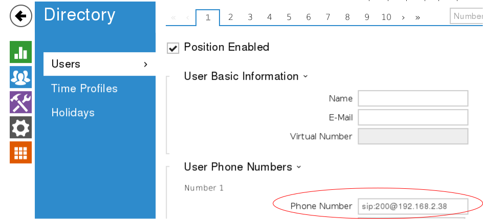
Go to the Trunk Numbers tab and click New to create a new Trunk Number, configure it as follows:

Trunk: Vega
Type of Number: Single Number (MSN)
Displayed Name: Your Analogue Line Telephone Number
Single Number (MSN): Your Analogue Line Telephone Number

Click OK to save this Trunk Number

Now go to the Trunk Groups tab and click New to create a new Trunk Group, configure it as follows:

Description: Vega
Sequence in Trunk Group: Vega

Click OK to save this Trunk Group

Step 3

This step assumes that your SIP Phones/Users are all using the CoS Default rule. If they are using a different CoS rule then please use the appropriate rule in the steps below

Go to the Numbering > User Settings > Class of Services tab and edit the CoS Default rule, and set as follows:

Automatic Outside Line: Enabled
Trunk Line Selection with Line Access Number: Click Add and select Vega from the drop down.

Click Apply to save the config.

Step 4

Go to Numbering > Call Distribution and on the Incoming Distribution tab you will see an entry of Type Single Number MSN, with your Analogue Line Telephone Number as the number. Edit this line and set as follows:

Assignment: Internal Number
Internal Number: Your SIP phone User number that you want to dial.

Setting it up as above will route any inbound calls directly to that specific phone. If you want to route it elsewhere then change the Assignment and route it accordingly, there are numerous ways to configure this which will not be covered in this guide.

Thats it!

You should now be able to dial out over your analogue line and inbound calls to your number will route according to your setup in Step 4.

Note: Step 3 configures the setting Trunk Line Selection with Line Access Number. This means that you will have to dial the access number to use this trunk. This setting can be found in the System Management > Access Codes. There is a setting there called Trunk Group Selection, click Add and select Vega from the Trunk Group drop down list. Set the Access Code to whichever number/numbers you want to use to route calls over your Vega/Analogue line.
e.g. Entering 9 in this box will require you to prefix your dialled number with a 9 in order to use this line.

If you have problems setting this up, please email support@provu.co.uk explaining which step you are up to and the problems you are facing.

Gigaset DECT Repeater Mode

Gigaset have recently released Firmware 42.194 for the N300 and N510 DECT Base Stations. With this release comes a change to the Repeater Mode setting, which is necessary for pairing DECT repeaters.

In the handset menu, under System > Settings, the Repeater Mode setting has been replaced by Encryption. This setting relates to the new Gigaset DECT repeaters in the EU which use encryption.
These are not available in the UK so you will most likely be using a DECT repeater that does not use encryption. You should therefore turn this setting OFF, to allow you to register the DECT repeater to the base station.

If you are still having trouble registering your repeater to the base, please take a look at our handy guide.

Using snom with Wireless Headsets

If you are using an EHS Advanced box to connect your wireless headset to your Snom phone, and are having difficulty getting it to work, you may find the answer to your problems below.

Snom have introduced a new setting in their latest firmware version 8.7.3.25 which relates to the use of headsets.

In the Advanced – Audio section of the Web UI you can now change the Headset Connection Method. If you are using an EHS box you will need to change this to Serial EHS Box in order to get the full functionality of the electronic hook switch.

For more information regarding headset compatibility head over to our website.

  • 1
  • 2