We have had an enquiry come in about how to wire in a tamper switch without an I/O module or a Wiegand module. I must admit I thought this was strange at first, given that I always thought it was fairly simple to do. It turns out it is but it is also easy to overcomplicate.
Make no mistake that 2N’s ideal setup would be a tamper switch connected to either an I/O module or a Wiegand module – every single piece of documentation I have found shows it connected in this manner. The idea is that it has 2 switches – we’ll call them switch 1 and 2 – with switch 2 connecting to the I/O module and back into the Verso, where it is recognised as a tamper switch, and switch 1 connecting to, for example, a 3rd-party alarm system, where it is recognised as a generic input that activates whatever the alarm system is programmed to activate.
The Verso however has its own generic input, into which you can wire switch 1 and have it behave as exactly that – a generic input.
Please note: in order to make use of a tamper switch in any way, you must have at least the Enhanced Integration Licence.
What you will need:
- A 2N Helios IP Verso base unit with or without camera – 9155101C or 9155101
- A tamper switch – 9155038
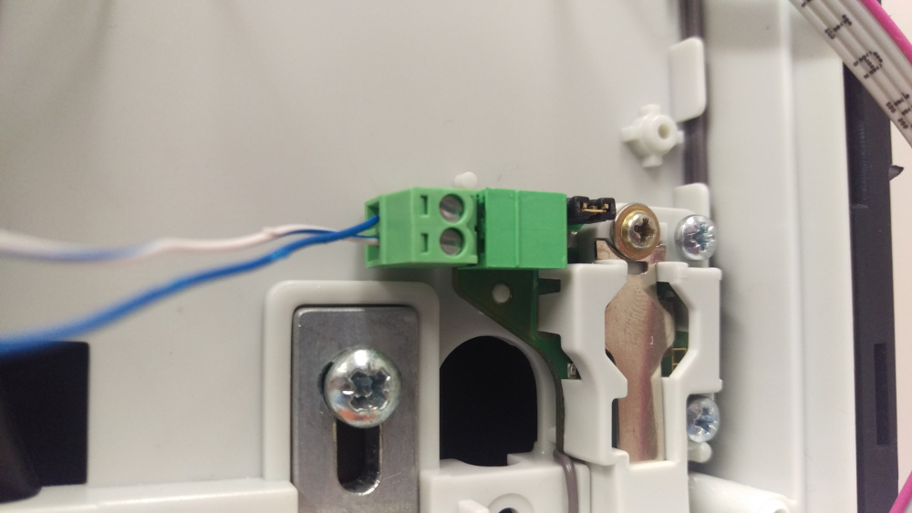
- 2 lengths of thin wire, about 6 inches long should do it – the lengths of wire I picked up for this demonstration are closer to about 6 feet.
- A small screwdriver
- Whichever other modules you wish to connect to the Verso – we have just an infopanel on our demo one.
- The relevant mounting boxes and/or frames – we are using a 2-module flush-mount box and frame.
- A computer on the network to do the programming.
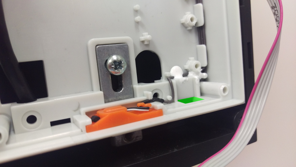
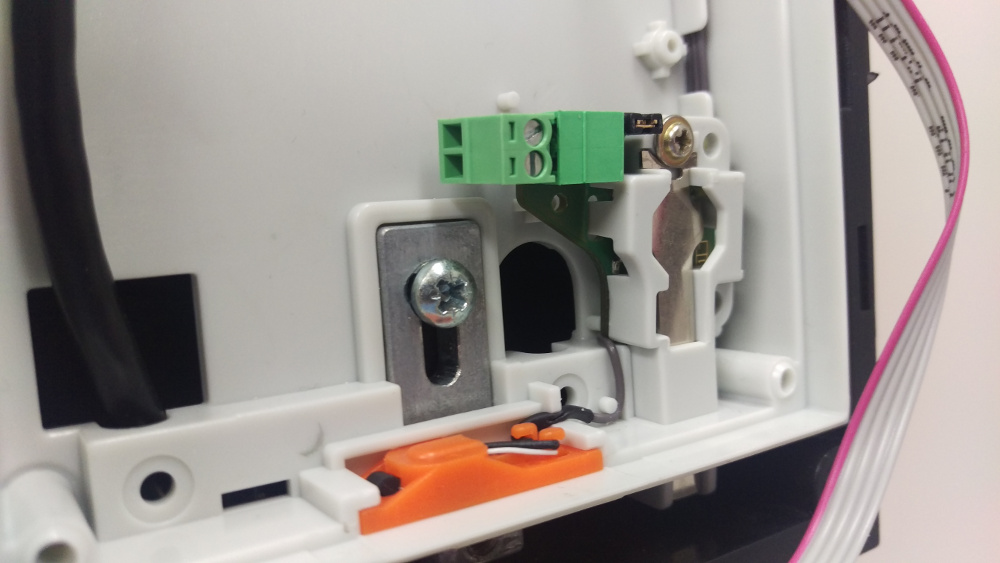
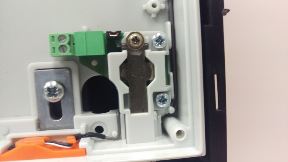
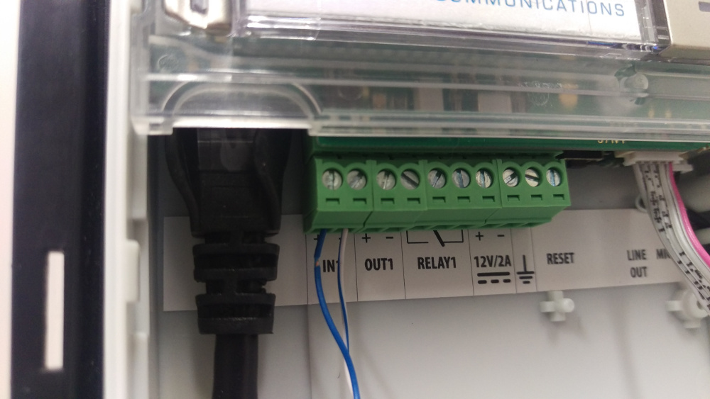
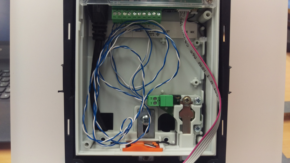
The tamper switch then needs wiring in via that little green terminal block on the left:
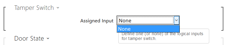
As mentioned earlier, because of the way it’s wired in, the Verso doesn’t know it is communicating with its own tamper switch, so the below is what you’ll see in the web interface when you try and program it as a tamper switch:
To run a quick demo of it working, I told the Verso that its Secured State Control was controlled by the status of input 1 – all this does short of any programming is activate a red LED next to the camera in the shape of a padlock – without the Enhanced Integration Licence this is all it will be able to do.
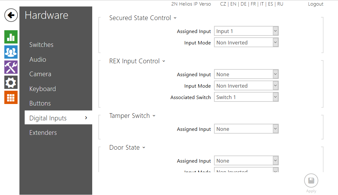
By using a screwdriver to press and depress the tamper switch, I was then able to turn the red LED on and off.
Please note: If you are using a tamper switch in this way you will not be able to wire anything else, such as an exit button, into the same input on the Verso. The only way to use an exit button without buying an I/O module will be to buy a security relay.