With growing interest in MS Lync, more people are moving to Lync online(Office 365) to benefit from the Microsoft feature rich platform. Some people think it’s a good investment and some think its not. Well I shall leave it to people to decide.
Coming back to the original subject, we are being asked if Snom Lync firmware supports Lync Online or not. The short answer at the moment is No. We understand all the customers requesting Lync Online (Office 365) support in Snom UC edition. The main challenge for Snom devices/development is a new additional login mechanism. To login to O365, Snom need to implement a new OrgID authentication method in their Lync firmware. By the way: in on-premise or Hosted-Edition deployments of Lync Server there is no such additional login using OrgID Authentication. Support for OrgID is on Snom’s roadmap, but an ETA is not available. We hope for the beginning of next year.
Personally, I expect that when we have O365 supported Snom firmware, clients will start requesting Lync On-Premise feature-set, that Snom as a device vendor wont be able to deliver(this may change). In other words OrgID support will be a resolution causing new “challenges”.
Please note: clients requesting phone support in O365 should carefully have a look on the O365 Plans (P1,P2,..,E1,E3,.. etc.) as only E4 support phone/pbx features/PSTN break out’s. E4 plan costs £17.75 per user per month. For the small organisation it’s reasonable but when you start adding more people to the system the cost increases to a level where it would be better to have an on-premises Lync device. Sangoma has recently introduced a Lync appliance that allows O365 integration along with a built-in VoIP gateway.
Find out more information on the Sangoma NetBorder Lync Express Gateway.
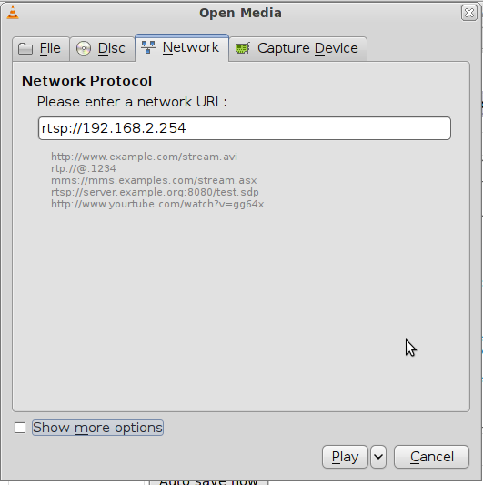 ” finally press the Play button.


 :
: :
: :
:
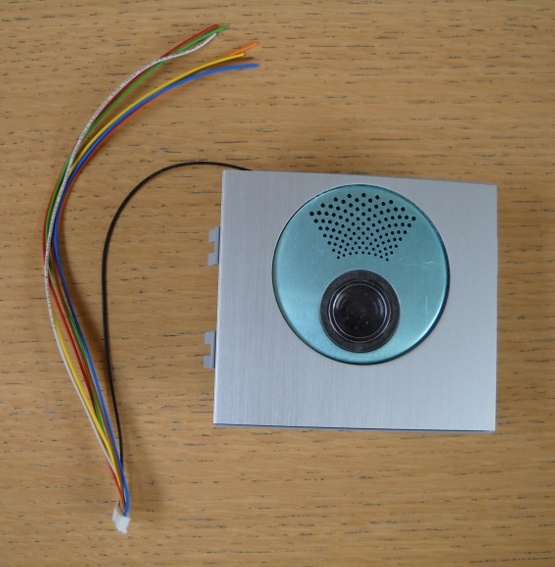
%> <%popup(20110603-DSCN0395.JPG)
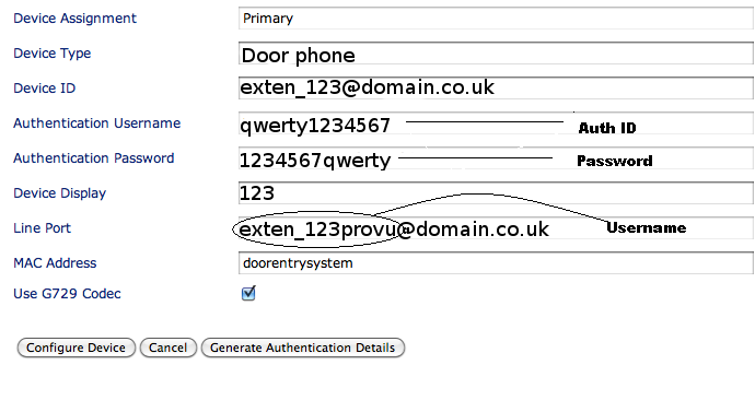 to see a snapshot showing require Broadsoft server user details.
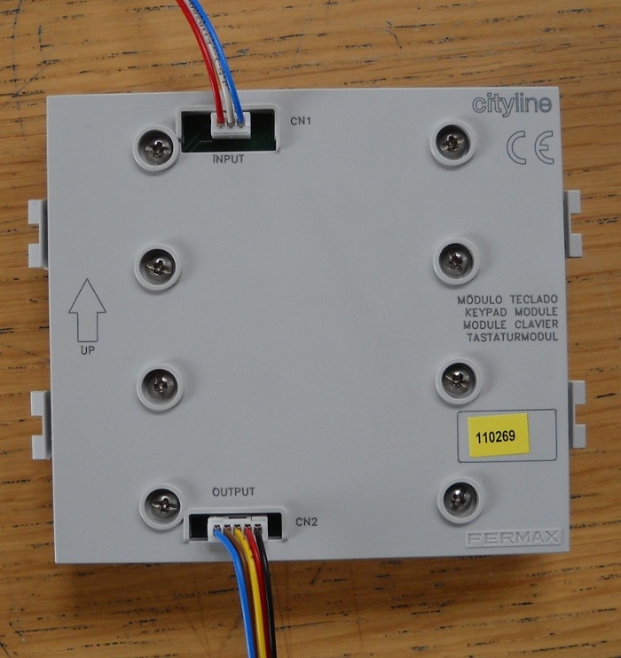
%> unit with<%popup(20110518-07438.jpg)