Browse Category

Technical Hints

Configuring a Sangoma Vega 3050G Gateway for use with 3CX

Firstly, log into your 3CX dashboard and navigate to the extensions tab on the left.

Create a new extension 

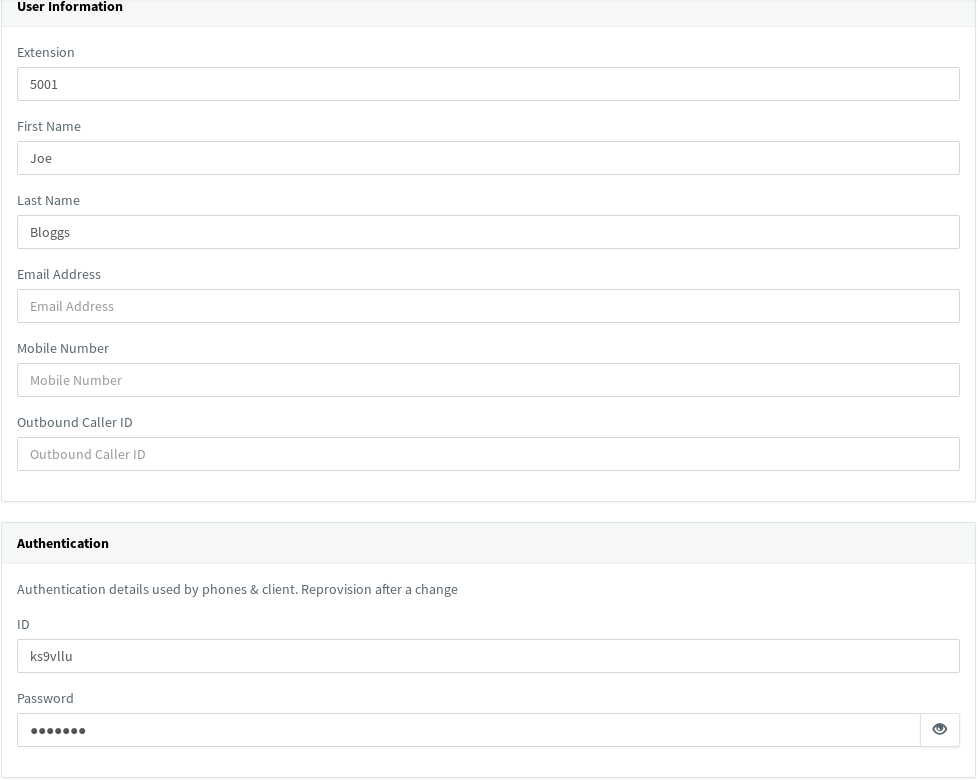
Replace the Authentication ID near the bottom with the extension number input at the top

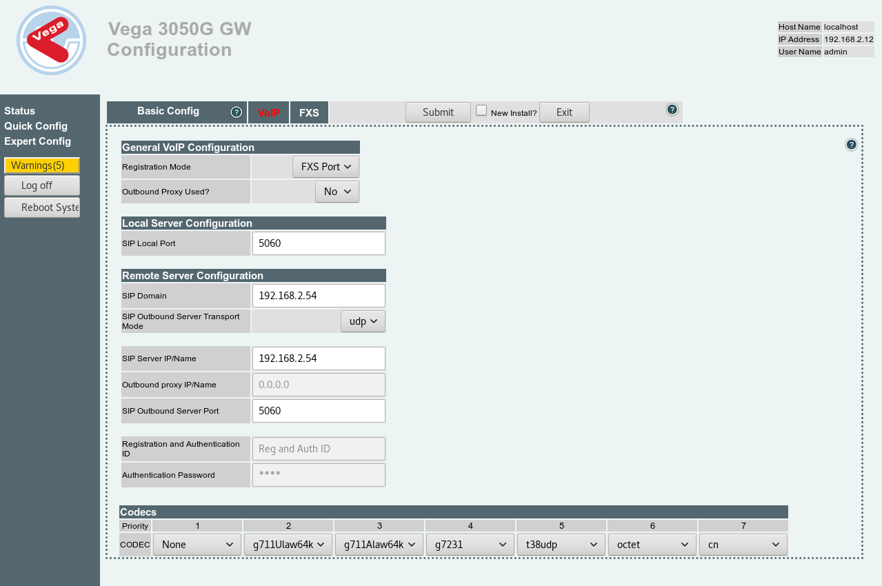
Now, in a new tab navigate to your Vega’s web interface and log in. Once at the dashboard, click Quick Config on the left hand side. From here, click VOIP and change the Registration Mode to FXS Port. Next, replace the SIP Domain & SIP Server IP/Name fields with the IP address of your 3CX server.

Note: We also advise changing the first CODEC at the bottom to from g729 to none, as shown below.

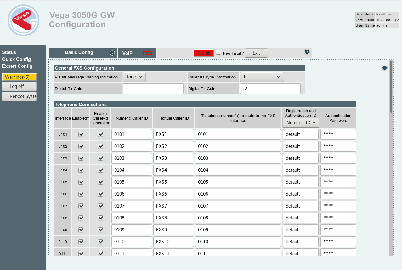
After that, navigate to the FXS tab. You will notice that all of the Telephone Connections are enabled as shown below.

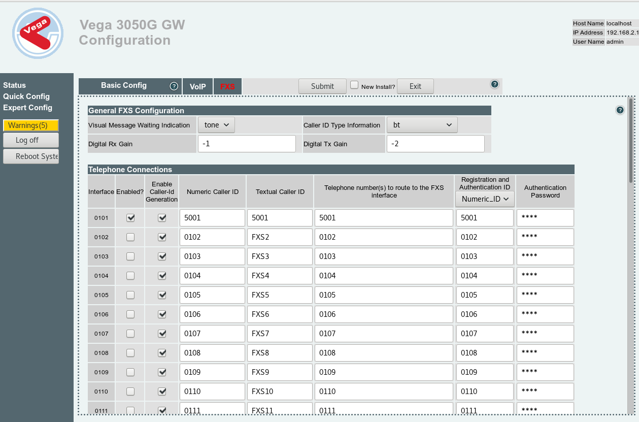
Disable all of the connections that you do not wish to use, and replace the Numeric Caller ID, Textual Caller ID, Telephone number and Registration and Authentication ID with the extension number, in this case 5001. Then type the authentication password in its respective field at the end of the row.

Return to your Extensions tab on 3CX. If you followed the guide correctly, there should be a green circle next to your new extension indicating that it has registered correctly and is ready to use.

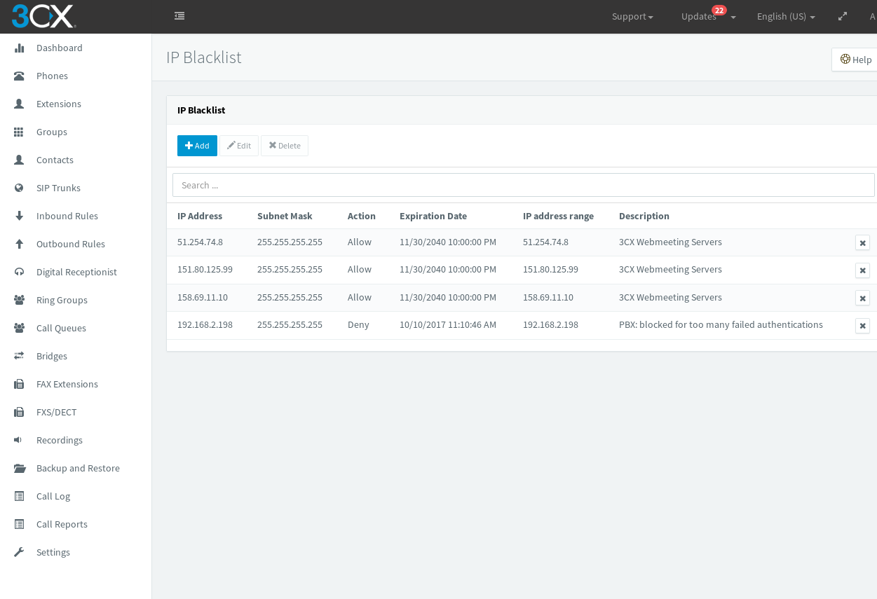
If it is still red, go to your 3CX Dashboard > IP Blacklist and ensure that your PBX server has not been blacklisted automatically, as show below. If this has occurred, simply select the Denied IP, click edit and change Deny to Allow.


How to route calls via prefixes on the 2N VoiceBlue Next

If you are using prefixes from your PBX in order to route out via different SIM cards you need to configure the voiceblue to be expecting this. The first thing you will need to do is assign the SIM cards to a GSM group. In this blog it’s configured for two SIM cards/prefixes.

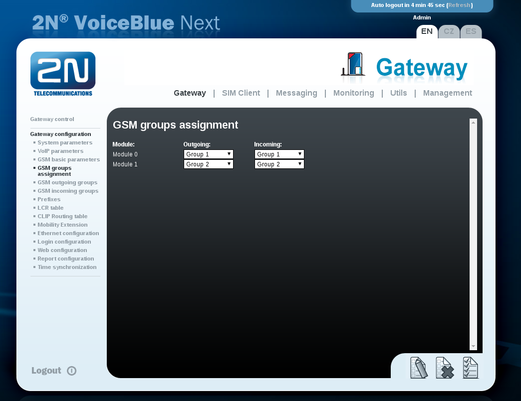
1. In the web user interface go to Gateway configuration > GSM group assignment and set each module to have their own group and press save.

2. Now we need to configure the prefixes that the voiceblue needs to be looking out for when a call gets sent to it. Under “Gateway configuration” go to “Prefixes” and then select one of the prefix tabs along the top.

2b) Once you’ve selected one of the Prefixlists we need to set the “Default count of digits” to the digit length we will be sending out via the SIM card and not how many are being sent to the voiceblue via the pbx. Example the voiceblue receives 12 digits and sends out 11 to the mobile network.

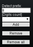
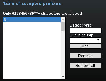
2c) Then we need to configure the table of accepted prefixes. This configures what prefix the voiceblue is looking for. In the “Detect prefix” field enter the desired prefix you are using then press “Add”. It should then appear in the list.

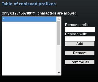
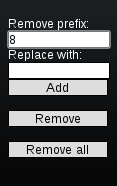
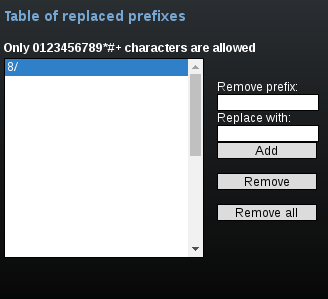
2d) Then we need to configure the “Table of replaced prefixes”. When the “/” is highlighted click the “Remove” button. Once removed in the “Remove prefix” field enter the desired prefix you are using and click the “add” button. Example: it should appear in the list as “8/”

2e) Once you’ve configured the above press save at the bottom and repeat for each prefix being used but remember to use a different list.

3a) Now we need to configure the LCR table. Go to “Gateway configuration” > “LCR table” and configure the first VoIP LCR by clicking the edit button.

3b) Then select the prefixlist that is going to be used for the first SIM group by editing “prefixlist or number of digits” with the prefixlist tab you configured earlier.

3c) We now need to configure the SIM group by going to “Groups/Tariffs” and selecting the required GSM group we created earlier.

3d) Press the OK button and then save the settings.

3e) Press the copy button for the VoIP LCR we just edited and then edit the prefixlist and GSM group as before for the second SIM routing and press OK and Save.

4) You should now be able to make calls via the desired SIM using prefixes on the voiceblue next.

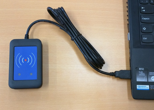
2N External RFID reader for 125kHz & 13.56MHz How-to Guide

In order to use the 2N RFID reader you need to install the correct driver software.  This is only available for Microsoft Windows and can be downloaded from this page:

https://www.2n.cz/en_GB/products/access-control/2n-access-unit#tab-2

Scroll down to the Documents section and you’ll see the driver listed in the “Software & Firmware” list.

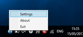
Once installed, you will see an icon in the task bar on your computer:

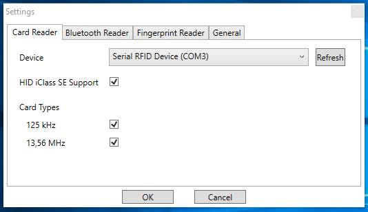
Right click this and select “Settings”.  This window will pop-up:

The device field may be empty, make sure you have the USB reader plugged in:

You may need to click refresh in the settings window.  Make sure you have the correct device selected before clicking “OK” to close that window.

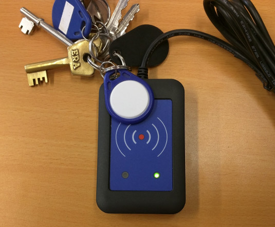
Now you can use the reader to scan compatible RFID/NFC cards into the 2N Access Commander software or in the web interface for 2N intercoms and access control devices.

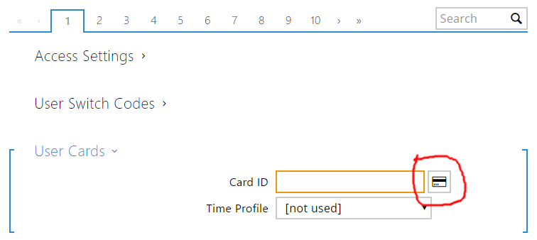
For example, in the web interface for an Access Control unit:

Click on the card icon and you will be prompted to scan a card:

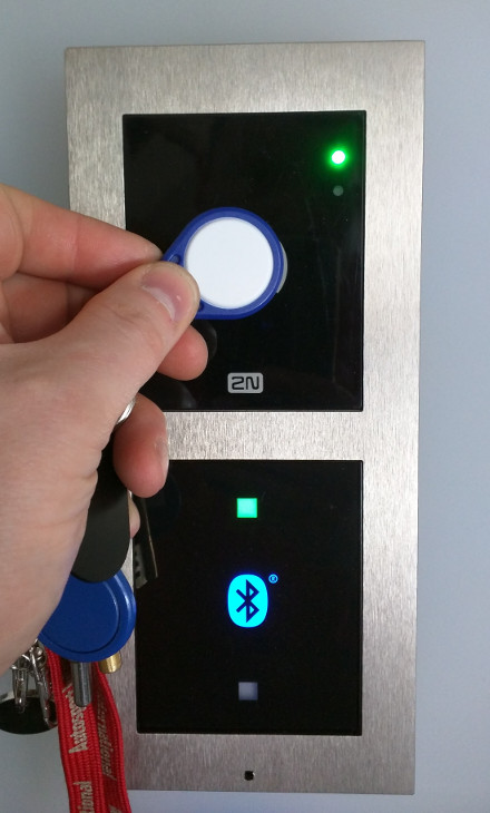
That’s it, you’ll now be able to use that device to open the door.

Gigaset DX800A Call Transfer Guide

Configuration:

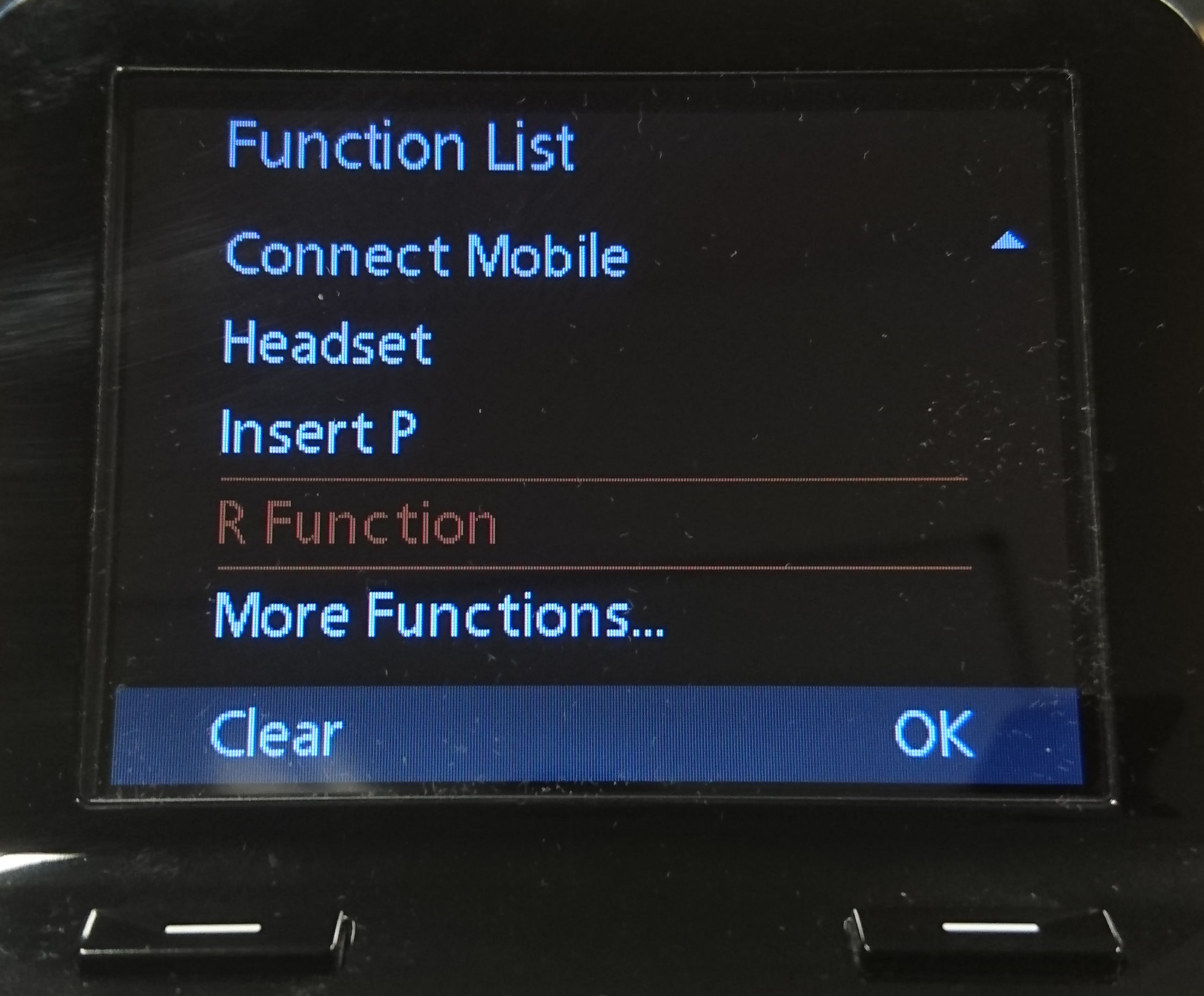
  1. Hold down a memory key for a few seconds until the function menu appears.
  2. Scroll down and select ‘R Function’.
  3. This will map the function to that memory key.
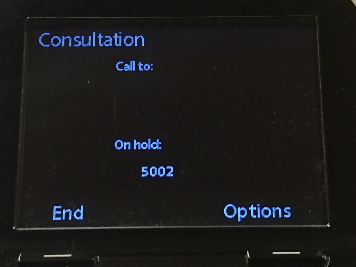
  4. When you want to transfer a call, press the memory key and a screen will appear. 
  5. Type in the number of the phone you want to transfer the call to and press the memory key again.
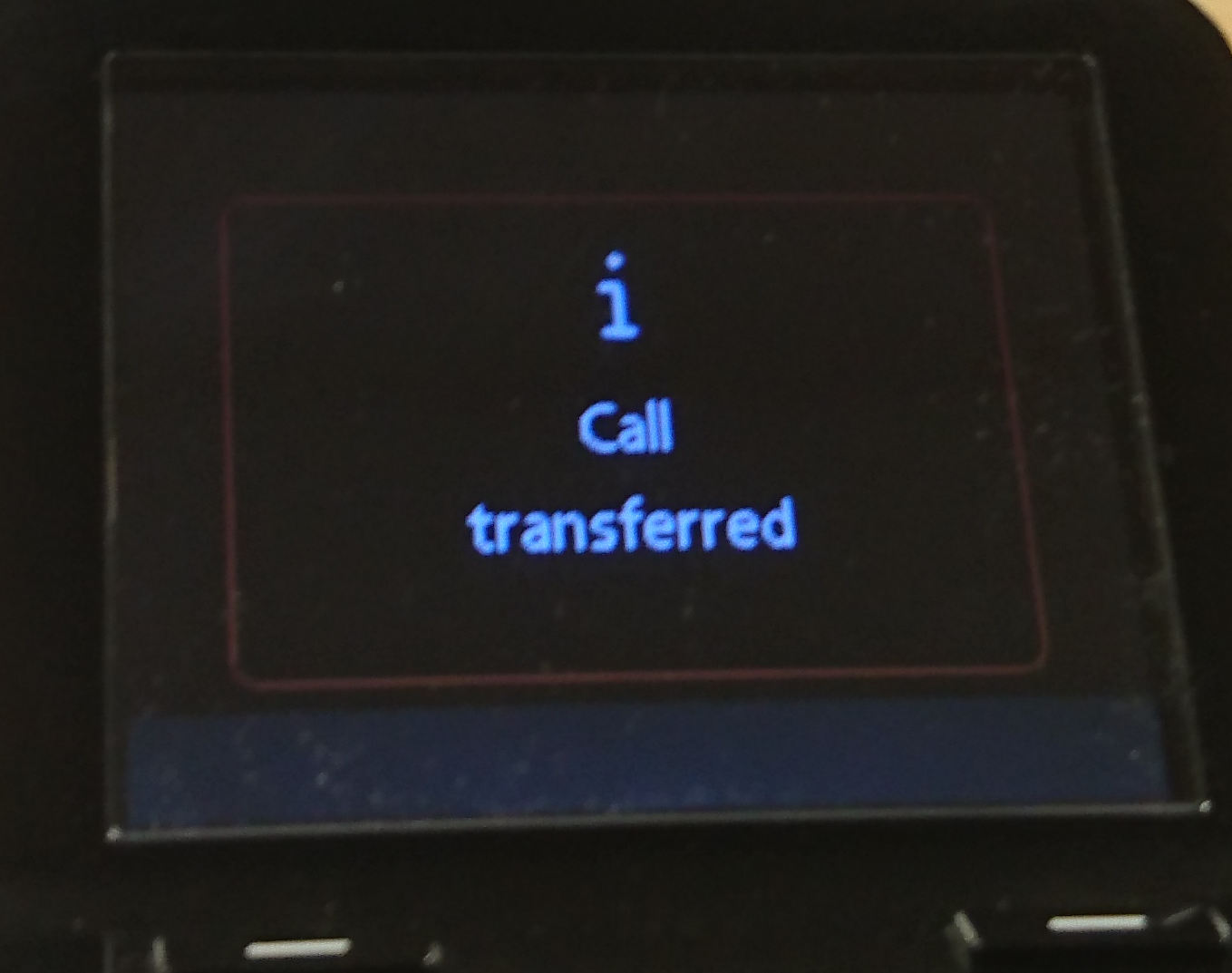
  6. You will get a screen like this to confirm the transfer has been successful:


Installation guide for 2N® 2Wire Kit

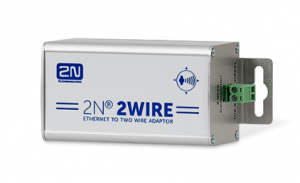
The 2N 2Wire adapter kit is extremely useful. Giving you the capacity to use exisiting 2 wire cable runs to connect IP devices to a network and power the device via PoE.
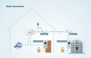
But it’s worth doing your homework so you can get the most out of them.

To help with this we have created this guide to help you get to grips with using them.

Essentially they are plug and play straight out of the box but……. this depends on how you want to use them.

Each 2Wire kit comes with two adapters and one power supply.

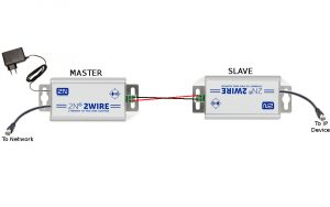
The solution works fundamentaly using a Master and Slave approach.

Any adapter that you connect the power supply to will become a Master.

Any adapter that you then connect to the Master via the 2wire connection becomes a Slave.

The Master should be connected to the network and the Slave connected to the IP device.

Any Master adapter can have up to 4 slaves connected to it.


Here we will look at three use case scenarios.

  1. Where a single Master & Slave set up is required on a single network.
  2. Where a single Master & multiple Slave set up is required on a single network.
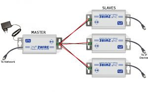
  3. Where multiple Master & Slave set ups are required on a single network.
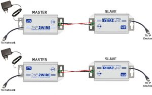
For the first two scenarios, where only a single Master adapter is required, the 2Wire kit is simply plug and play.

PLEASE BE AWARE that in the case of scenario 3, where multiple Master adapters are required on a single network, a pairing procedure must be executed.

If you connect multiple Master adapters to a single network without performing the necessary unpairing/pairing procedures YOU MAY EXPERIENCE NETWORK CONFLICT ISSUES.

Good thing is….. the unpairing/pairing procedure is very simple. Here we will guide you through it.


First let’s take a look at how to connect a single Master and Slave set up.
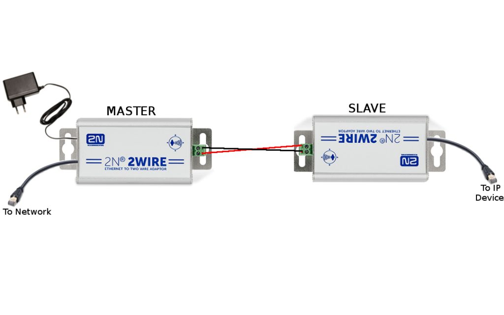
This is the simplest configuration and works straight out of the box.

Just make sure you connect the 2 wire correctly to each adapter. Positive to positive & negative to negative.


Now let’s take a look at how to connect multiple Slaves to a single Master.
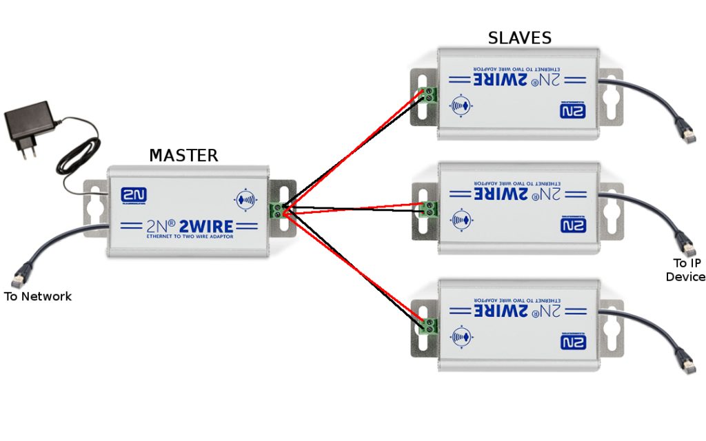
This is similar to a single Master / Slave configuration in that it works straight out of the box. Multiple Slaves can be wired into a single Master.

Again make sure to connect the 2 wire correctly to each adapter. Positive to Positive & negative to Negative.


Finally we have the multiple Masters & multiple Slaves on a single network configuration.
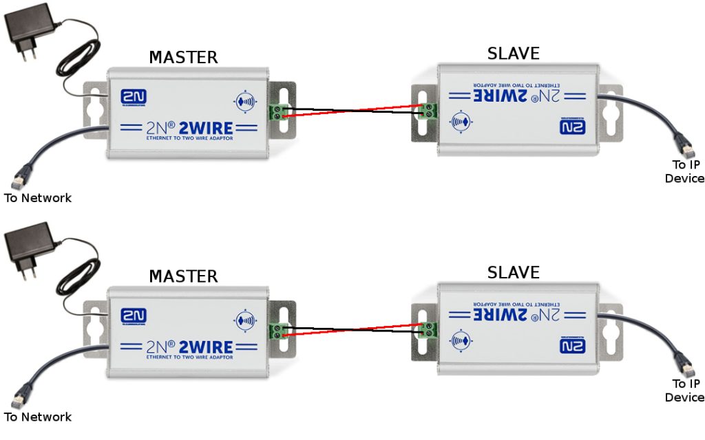
If this configuration is required and you are installing multiple Master adapters on to a single network, it is very important to perform an unpairing/pairing procedure. If you do not you may experience network conflict issues.


Unpairing and Pairing your adapters

Each adapter has a small hole labelled ‘Grp’. There is a button inside this hole that is used to initiate the unpairing/ pairing procedures.

To access the button you will need a small screwdriver or similar tool.
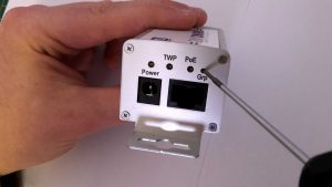
To perform unpairing/pairing procedures the adapters must be powered.

So you must connect the power supply to the Master and connect the Slave via the 2 wire connection.

But DO NOT connect them to the network or the IP device….. yet.

To unpair an adapter press and hold the ‘Grp’ button for 10 seconds, until you see all lights on the adapter go off.

After unpairing is complete you should see only the power light illuminated.

You should do this on all adapters before attempting a pairing procedure.

To perform a pairing procedure press and hold the ‘Grp button for 2 seconds. When you release the button the ‘TWP’ light will begin steadily blinking letting you know that the adapter is in ‘seek’ mode and is looking for another adapter to pair to.

Once an adapter has found another adapter to pair to the ‘TWP’ will become static, letting you know pairing is complete.

In a single Master & single Slave pairing it doesn not matter which adapter you put into pairing/seek mode first.

But if you wish to have multiple Slaves connected to a single Master, then you must connect all Slaves via the 2Wire connection to the Master first, then run individual pairing procedures for each connected Slave.

To do this you must initiate the pairing/seek mode on the Master first and then the first Slave.

Then repeat this for each Slave connected to the Master.

But remember, unpairing & pairing is only needed when installing more than one Master adapter on a single network. 


Thanks for reading.


How to configure Snom 720 with Plantronics CS520 and EHS Advanced V2.0

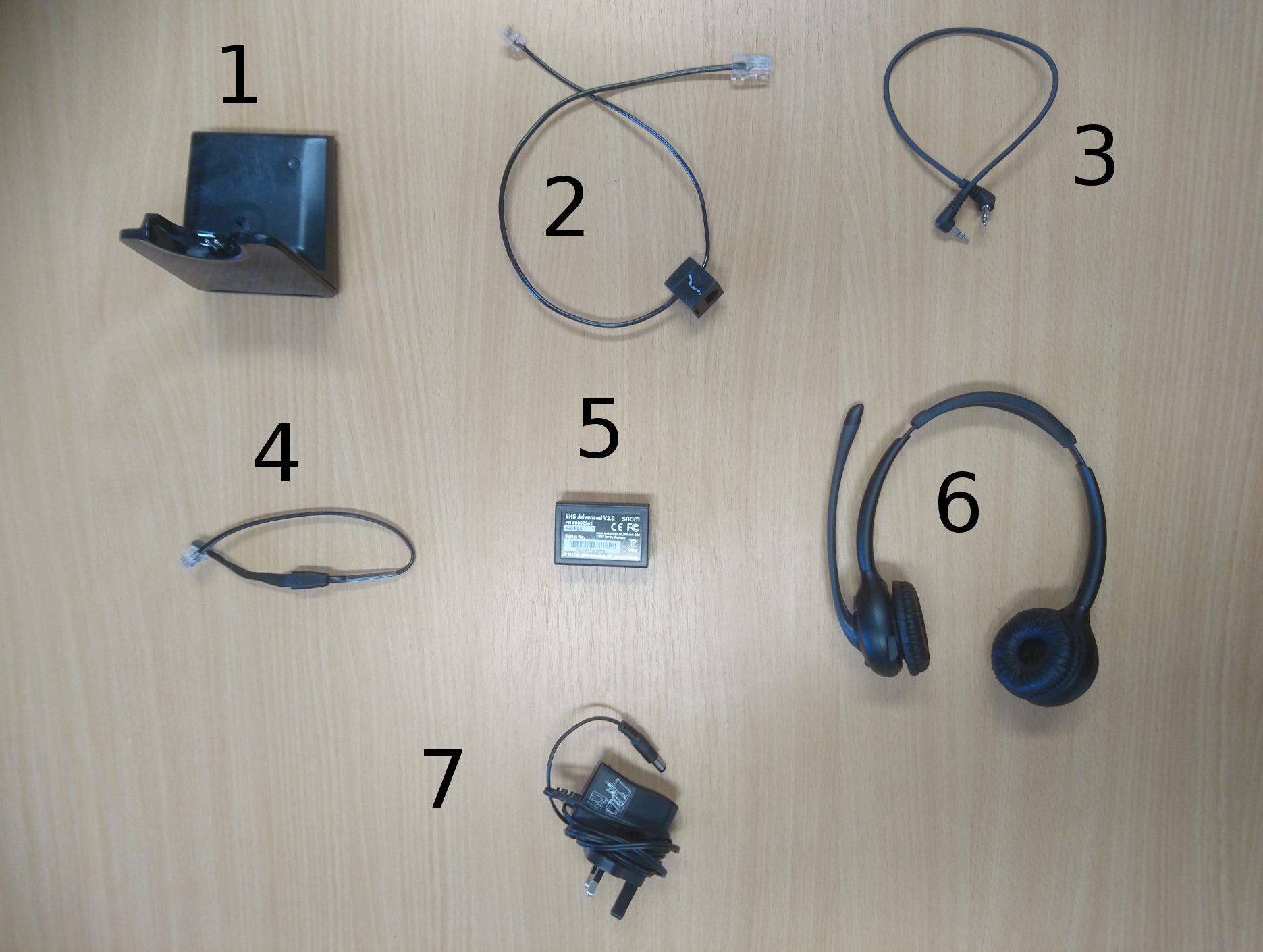
List of Components:

  1. Plantronics Base
  2. Plantronics Cable
  3. 3.5mm DC Jack
  4. Snom 4 Pin Connector
  5. Snom EHS Advanced V2.0 Adapter
  6. Plantronics Headset
  7. Plantronics Base Power Supply

Configuration:

  1. Connect the Plantronics Base(1) to the Plantronics Base Power Supply(7).
2. Connect the Snom EHS Adapter(5) to the 3.5mm DC Jack(3). Note that only the DC Jack goes into this end of the EHS Adapter, you do not need to plug anything else into this end.

3.  Connect the Snom EHS Adapter(5) to the Snom 4 Pin Conector(4).

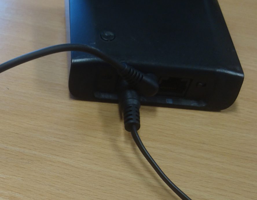
4. Connect the other end of the 3.mm DC Jack(3) into the back of the Plantronics Base(1).

5. Connect the Plantronics Cable(2) to the back of the Plantronics Base(1).

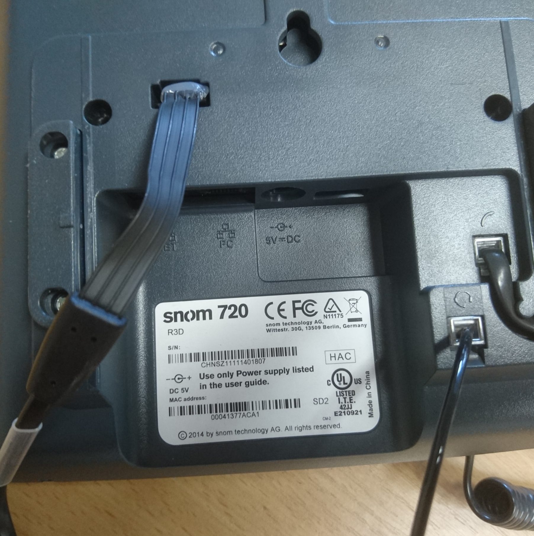
6. Connect the other end of Snom 4 Pin Connector(4) into the slot in the picture below. Then connect the other end of the Plantronics Cable(2) into the Headset port, making sure you Do Not put it into the handset port by mistake.

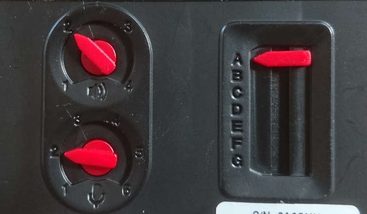
7. Check the Dial settings on the bottom of the Plantronics Base(1) to make sure that they match the picture below. 

8. The headset should be ready to use. No phone settings should need to be changed, just make sure that all connections are secure and that you have power to the headset base.

Konftel 300Wx firmware upgrade

When using a Konftel 300Wx with a Gigaset N300IP or N510IP it may be necessary to upgrade the 300Wx to the latest firmware.  If you are having problems making or receiving calls this should sort it.

  1. Go to go the Konftel firmware download page: http://www.konftel.com/Support/Upgrade
  2. Select “Konftel 300Wx” and scroll down to the bottom of the page
  3. Download the latest firmware version for use with SD card.  The version is 1.9.8 at the time of writing
  4. Then download the “DECT module” firmware.  The version of this is 932 at the time of writing
  5. Put both files onto a FAT formatted SD card in the root folder
  6. Insert the SD card into the 300Wx, navigate to the settings menu and select the upgrade mode option
  7. Press and hold the “hold” key on the 300Wx (bottom left of the keypad)
  8. Follow the instructions on screen
  9. Once the firmware image upgrade has completed, go back into “menu” -> “Settings” -> “Upgrade Mode” and this time select DECT
  10. Wait approx 3 minutes for the upgrade to complete
  11. Finally, reboot the 300Wx


How to configure Yealink T46G with Plantronics CS520 and EHS36

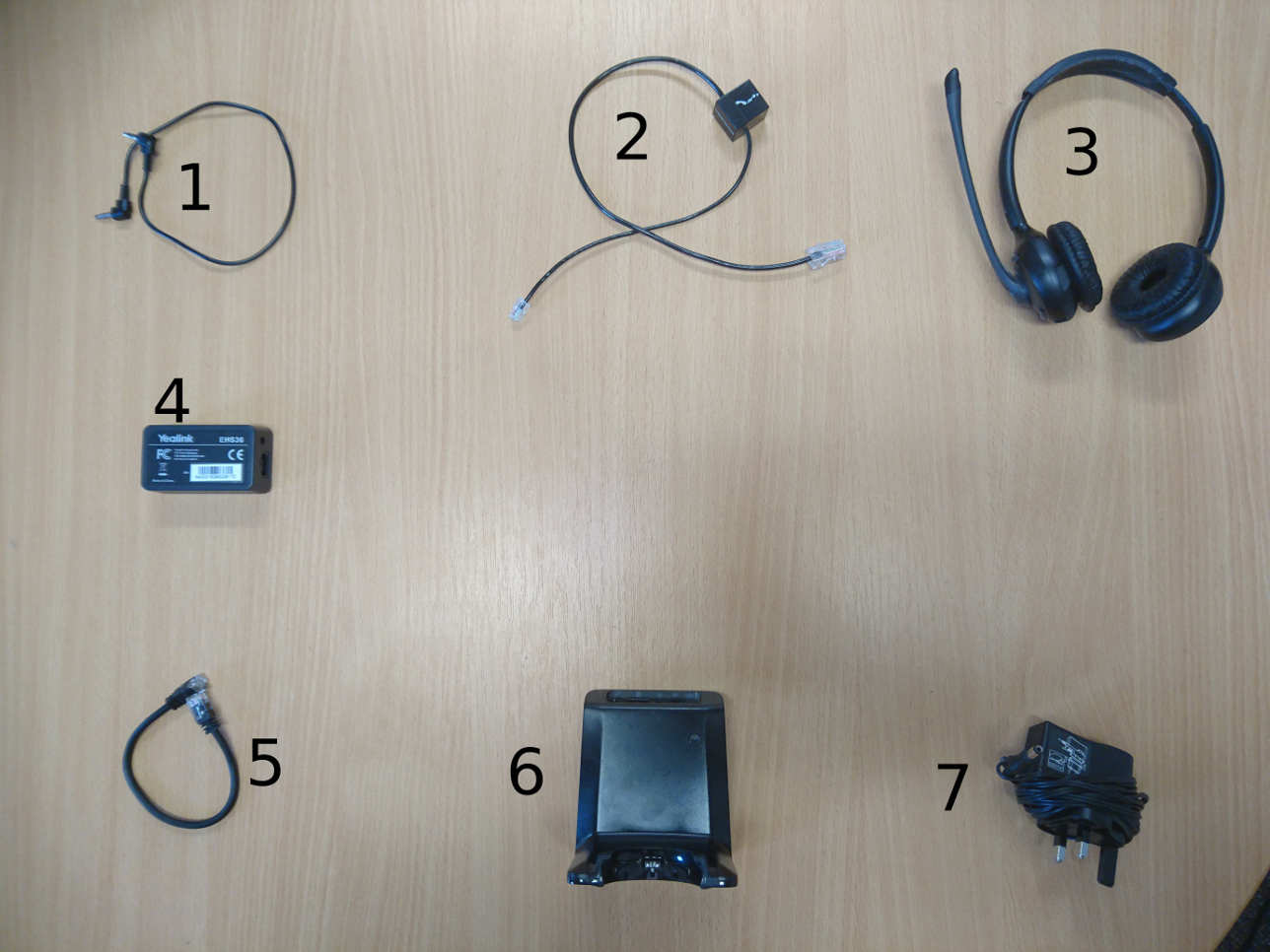
List of Components:

  1. 3.5mm DC Jack
  2. Plantronics phone cord
  3. Plantronics CS520 Headset
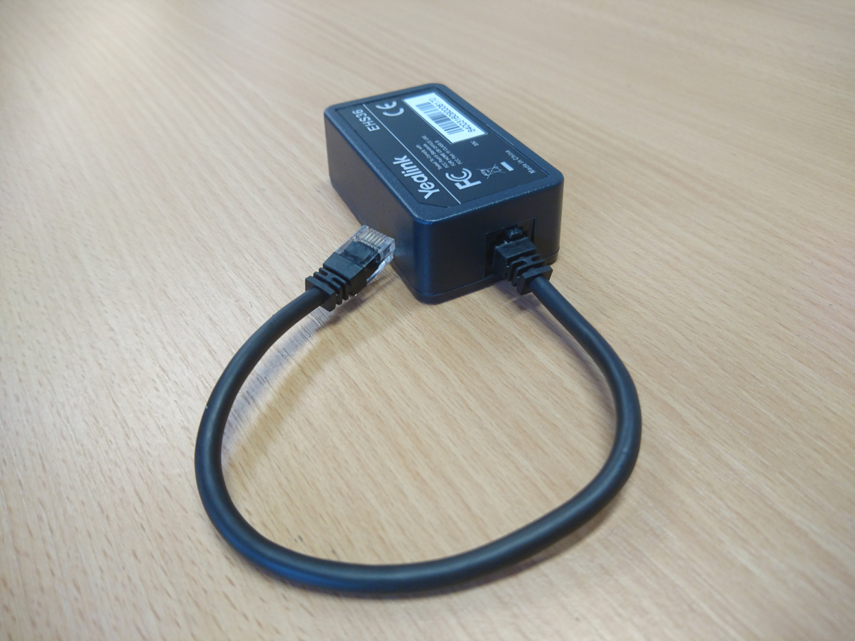
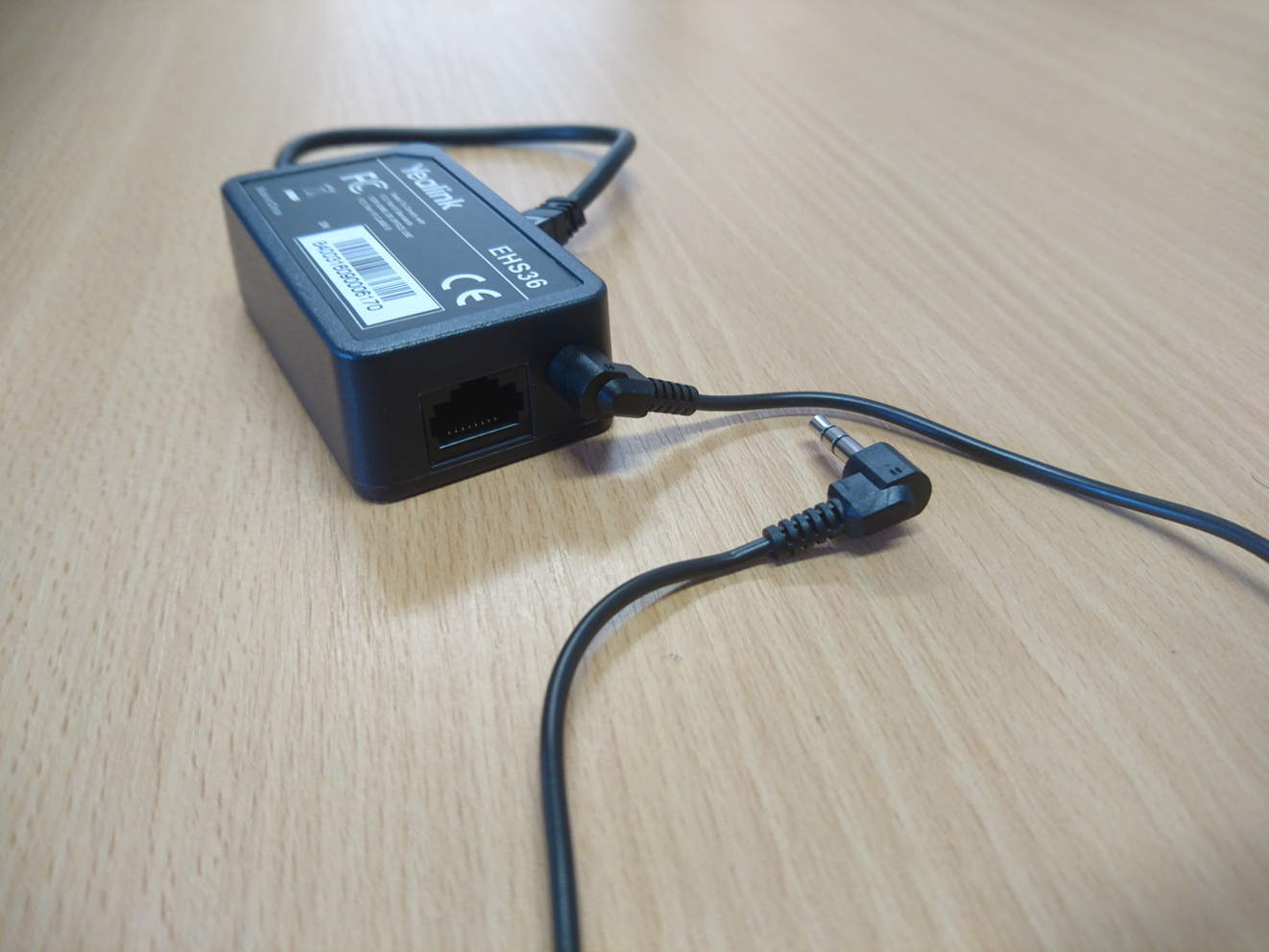
  4. Yealink EHS36 Adapter
  5. RJ12 Cord
  6. Plantronics Base
  7. Plantronics Base power supply

Configuration:

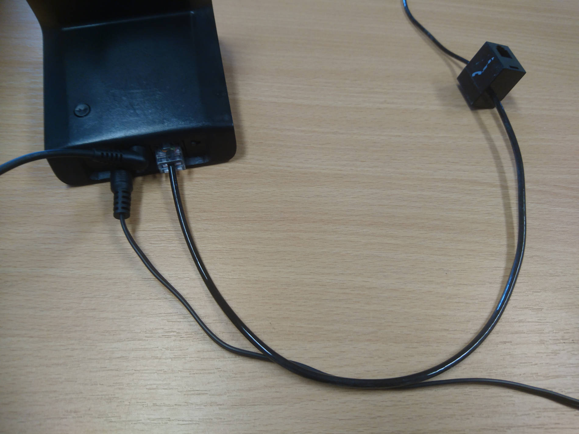
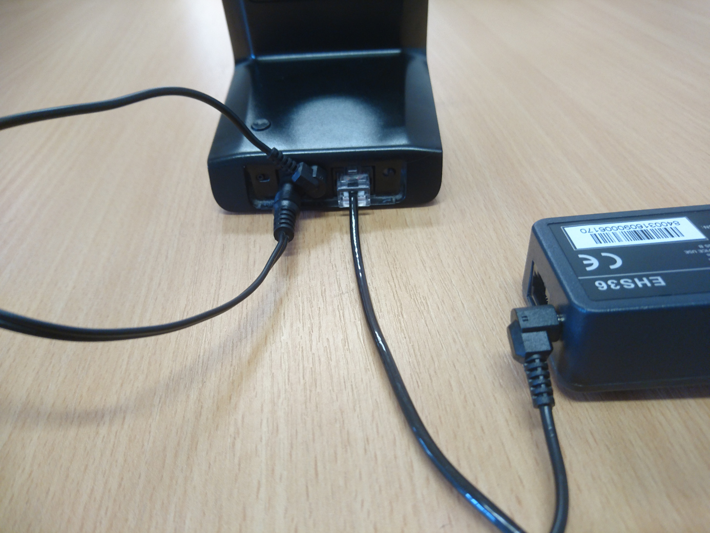
  1. Connect the RJ12 Cord (5) to the Yealink EHS36 Adapter(4).

2. Connect the 3.5mm DC Jack(1) to the Yealink EHS36 Adapter(4). Note that you only need the DC Jack in this end, you do not need to fill this socket.

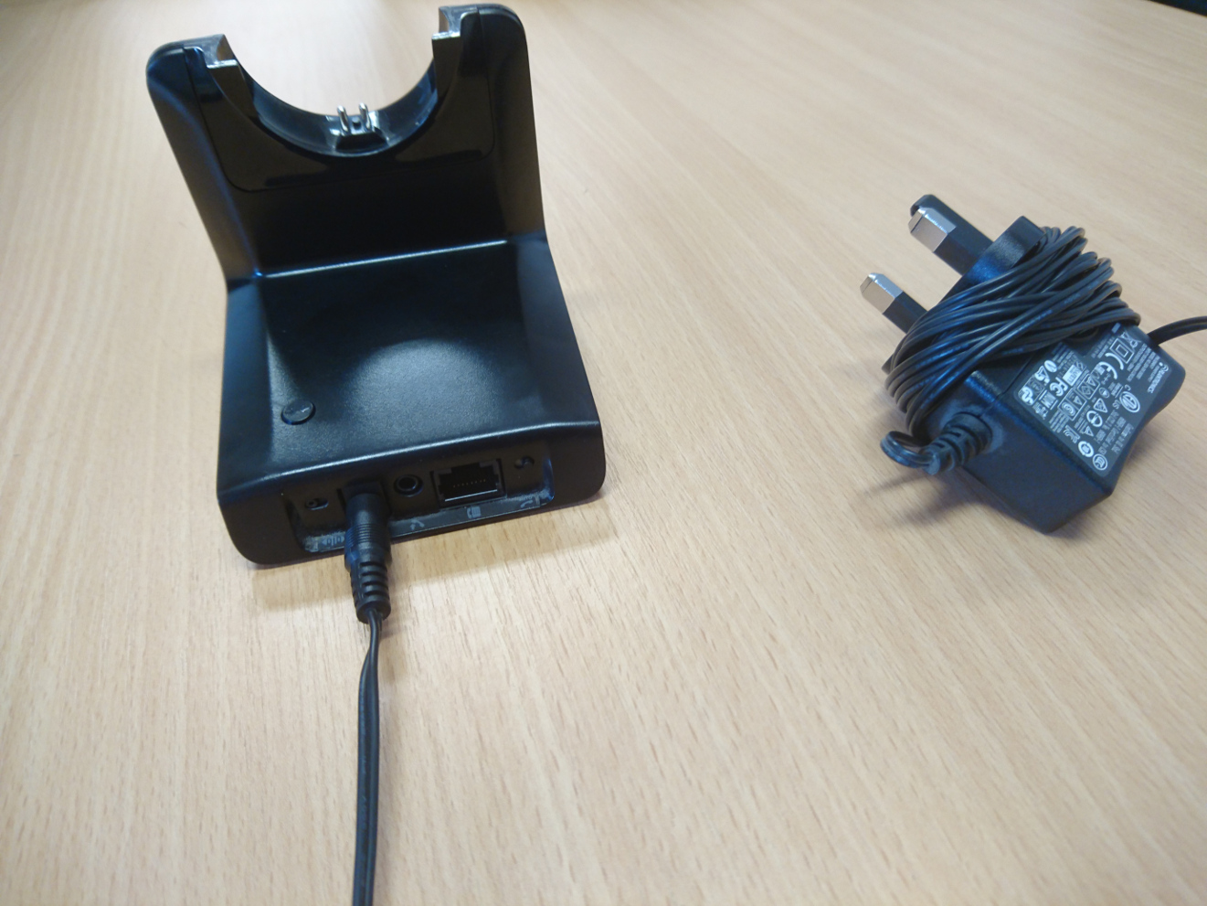
3. Connect the Plantronics Base(6) to the power supply(7).

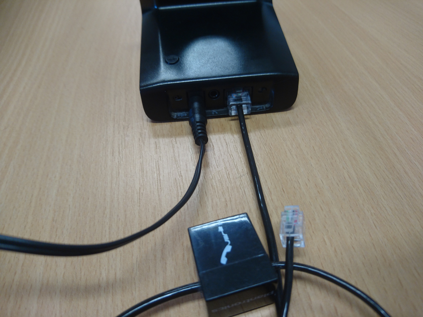
4. Connect the Plantronics phone cord(2) to the Plantronics Base(6).

5. Connect the 3.5mm DC Jack(1) to the Plantronics Base(6).

6. Connect the RJ12(5) to the EXT port on the back of the Yealink T46G. Then connect the Plantronics phone cord(2) to the headset port on the back of the phone; making sure you don’t put it in the handset port by mistake.

You shouldn’t need to change any of the settings in the phone as the Yealink EHS36 should work out of the box. However, you will want to check that on the bottom of the Plantronics base that the Dial’s are set correctly. This should be the correct setting for the dials :

Sangoma PBXact UC – User Control Panel (UCP)

Are you interested in finding out more about how the User Control Panel (UCP) works on a Sangoma PBXact UC system? Please see the following guide below on how to set this up and have this up and running in minutes:

This guide shows you how to create a user and set up UCP for an extension that already exists. If you would like to find out how to create an extension, please refer to the following link:

https://blog.provu.co.uk/sangoma-pbxact-uc-creating-an-extension/

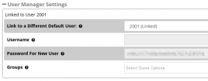
Please note, if you have already created an extension on a PBXact UC system, you may already have a user created in the ‘User Manager’ section.

The screenshot to the right shows the ‘User Manager Settings’ section on the screen where you create an extension:
Step 1:

You will need to start by web browsing to the IP address of your PBXact system using a web browser of your choice. Once you have browsed to the PBXact UC system, you should see the homepage with the following options to choose from.

You will need to select ‘PBX Administration’ which is the first option on the left hand side of the interface.

Step 2:

You should now see a screen prompting you to enter a username and password. If you don’t know the username and password, you may need to consult an administrator.

Step 3:

Providing you have entered the correct username and password, you should see a system overview of the PBXact UC system.

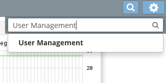
Using the search bar at the top right hand side of the interface, you will need to search of ‘User Management’. Please see the screenshot below that shows this:

Step 4:

Once you have opened the ‘User Manager’, you will need to click on ‘Add’.

Step 5:

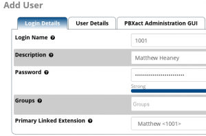
You should now see the options for creating a new user. You will then need to input a login name, description for the user, a secure password and also link the extension to an extension already created on the PBXact UC system.

Step 6:

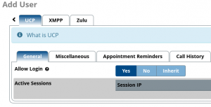
For this step, you will need to scroll along the tabs using the arrow keys located near the top right hand side of the interface. You should then see some further options on the tabs including ‘UCP’.
Please click onto the ‘UCP’ tab which should display the following screen.

You will need to ensure that you change the ‘Allow Login’ to ‘Yes’ in order to log into the User Control Panel once the user has been created on the system.

Step 7:

Under the ‘UCP’ section, you should also see some additional options. Please see the screenshot below that show some of the other settings.

You may want to enable a user to be able to make calls via the User Control Panel. To do this, y
ou will need to navigate to ‘Miscellaneous’, then select ‘Yes’ under the option ‘Enable Originating Calls’.

Please note that there are other options that can be configured through these settings such as enabling conferences, voicemail settings and other options.

Step 8:

Once you have finished enabling the settings that you would like to be enabled for the user, you can go ahead and submit the changes by pressing the ‘Submit’ button located near the bottom right hand side of the screen.


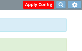
You should now be taken back to the ‘User Manager’ home screen, which should display the option to ‘Apply Config’ at the top right hand side of the screen.

This is the end of the configuration process for enabling ‘UCP’ for a user. Please see the following steps below for logging into the ‘User Control Panel’:

Step 9 (Logging In):

If you are still logged into the PBXact UC system, you should see an option for ‘UCP’ using the tabs at the top of the screen.

Clicking onto the ‘UCP’ tab should open the ‘User Control Panel’ in a separate tab as shown in the screenshot below:

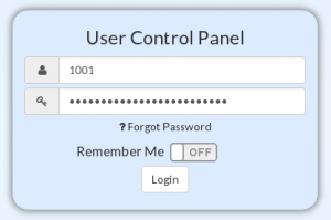
The login page for the ‘User Control Panel’ should now be displayed prompting you to enter a username and a password.

You will need to enter the user extension number and the password that was set on the fifth step of the configuration above and hit ‘Login’.

Providing you have entered the correct username and password, you should see the following screen or similar screen as shown below:

Please note that the options shown on the sidebar on the left hand side of the screen may vary depending on the settings that have been enabled/disabled.

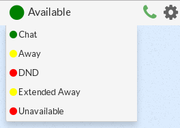
You should be able to change settings such as presence for the extension you are logged in as by selecting the icon shown in the screenshot below: