Are you interested in finding out more about how the User Control Panel (UCP) works on a Sangoma PBXact UC system? Please see the following guide below on how to set this up and have this up and running in minutes:
This guide shows you how to create a user and set up UCP for an extension that already exists. If you would like to find out how to create an extension, please refer to the following link:
https://blog.provu.co.uk/sangoma-pbxact-uc-creating-an-extension/
Please note, if you have already created an extension on a PBXact UC system, you may already have a user created in the ‘User Manager’ section.
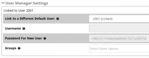 The screenshot to the right shows the ‘User Manager Settings’ section on the screen where you create an extension:
Step 1:
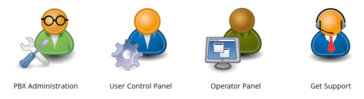
You will need to start by web browsing to the IP address of your PBXact system using a web browser of your choice. Once you have browsed to the PBXact UC system, you should see the homepage with the following options to choose from.

You will need to select ‘PBX Administration’ which is the first option on the left hand side of the interface.
Step 2:
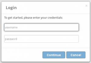
You should now see a screen prompting you to enter a username and password. If you don’t know the username and password, you may need to consult an administrator.
Step 3:
Providing you have entered the correct username and password, you should see a system overview of the PBXact UC system.
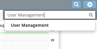
Using the search bar at the top right hand side of the interface, you will need to search of ‘User Management’. Please see the screenshot below that shows this:
Step 4:
Once you have opened the ‘User Manager’, you will need to click on ‘Add’.

Step 5:
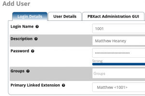
You should now see the options for creating a new user. You will then need to input a login name, description for the user, a secure password and also link the extension to an extension already created on the PBXact UC system.
Step 6: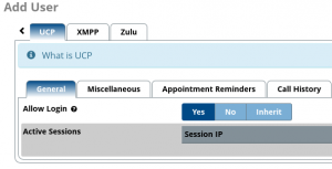
For this step, you will need to scroll along the tabs using the arrow keys located near the top right hand side of the interface. You should then see some further options on the tabs including ‘UCP’.
Please click onto the ‘UCP’ tab which should display the following screen.
You will need to ensure that you change the ‘Allow Login’ to ‘Yes’ in order to log into the User Control Panel once the user has been created on the system.
Step 7:
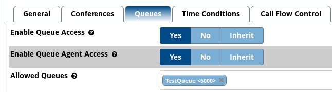
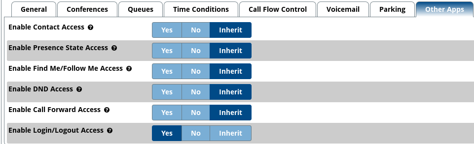
Under the ‘UCP’ section, you should also see some additional options. Please see the screenshot below that show some of the other settings.
![]()
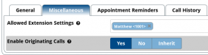 You may want to enable a user to be able to make calls via the User Control Panel. To do this, y
ou will need to navigate to ‘Miscellaneous’, then select ‘Yes’ under the option ‘Enable Originating Calls’.
Please note that there are other options that can be configured through these settings such as enabling conferences, voicemail settings and other options.
Step 8:
Once you have finished enabling the settings that you would like to be enabled for the user, you can go ahead and submit the changes by pressing the ‘Submit’ button located near the bottom right hand side of the screen.
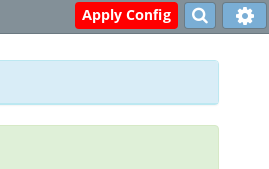
You should now be taken back to the ‘User Manager’ home screen, which should display the option to ‘Apply Config’ at the top right hand side of the screen.
This is the end of the configuration process for enabling ‘UCP’ for a user. Please see the following steps below for logging into the ‘User Control Panel’:
Step 9 (Logging In):
If you are still logged into the PBXact UC system, you should see an option for ‘UCP’ using the tabs at the top of the screen.
![]()
Clicking onto the ‘UCP’ tab should open the ‘User Control Panel’ in a separate tab as shown in the screenshot below:
![]()
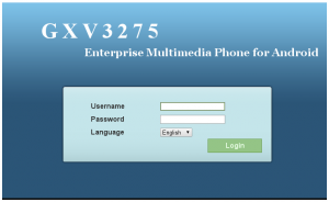
The login page for the ‘User Control Panel’ should now be displayed prompting you to enter a username and a password.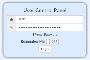
You will need to enter the user extension number and the password that was set on the fifth step of the configuration above and hit ‘Login’.
Providing you have entered the correct username and password, you should see the following screen or similar screen as shown below:
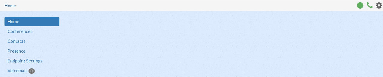
Please note that the options shown on the sidebar on the left hand side of the screen may vary depending on the settings that have been enabled/disabled.
You should be able to change settings such as presence for the extension you ar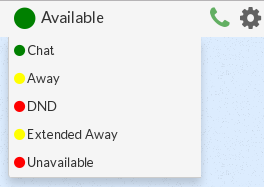 e logged in as by selecting the icon shown in the screenshot below:


 s at the top of the page.
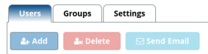 een which may list users below if you already have users registered on the system.
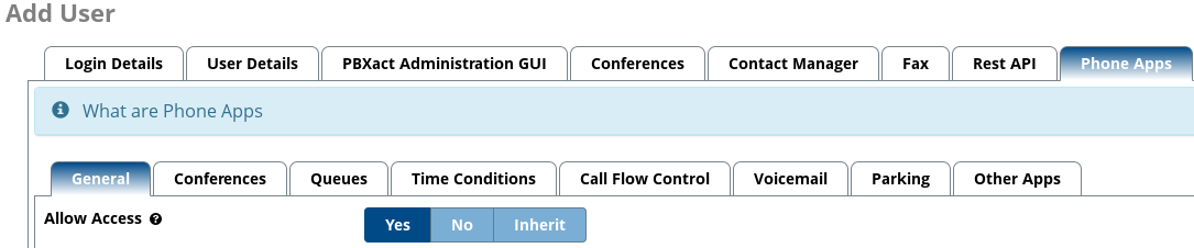