The steps below will show you how to enable EHS both through the phones interface and the web interface on your Fanvil phone.
Phone Interface
Step 1:
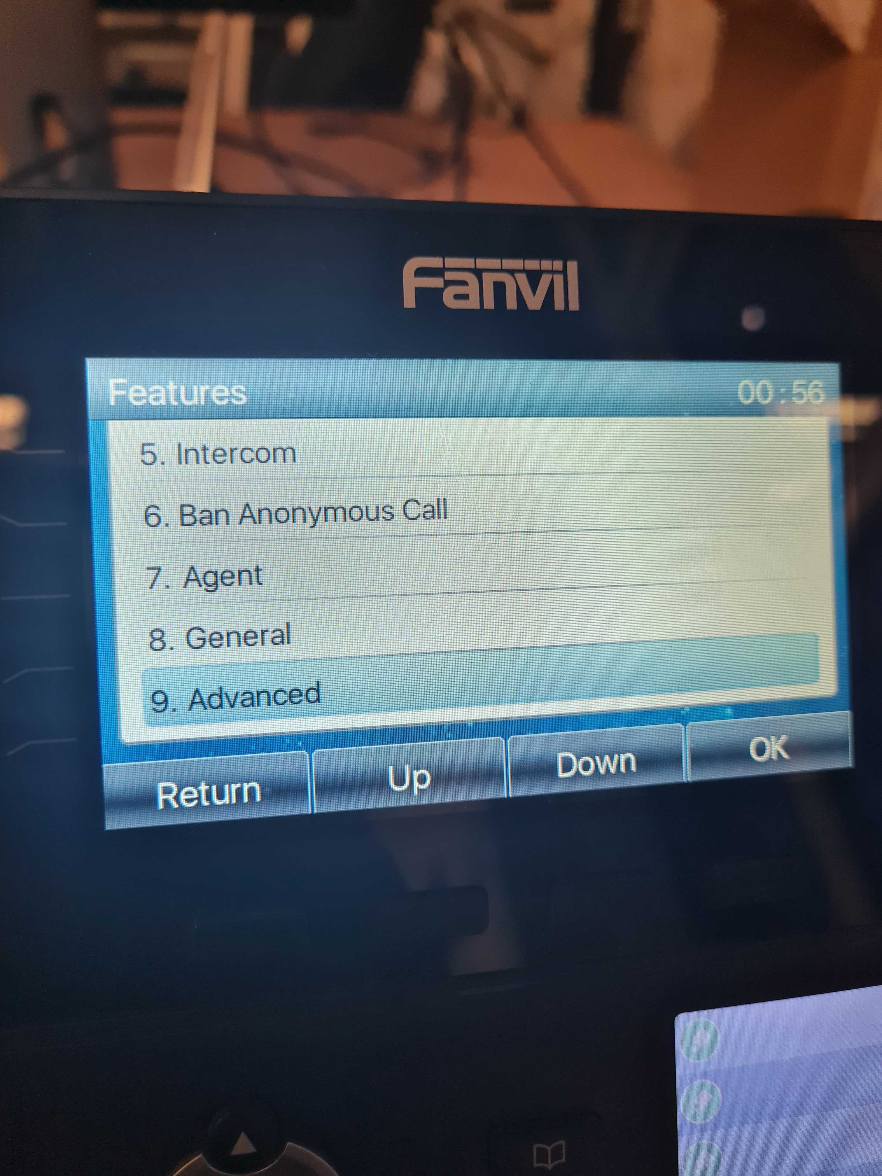
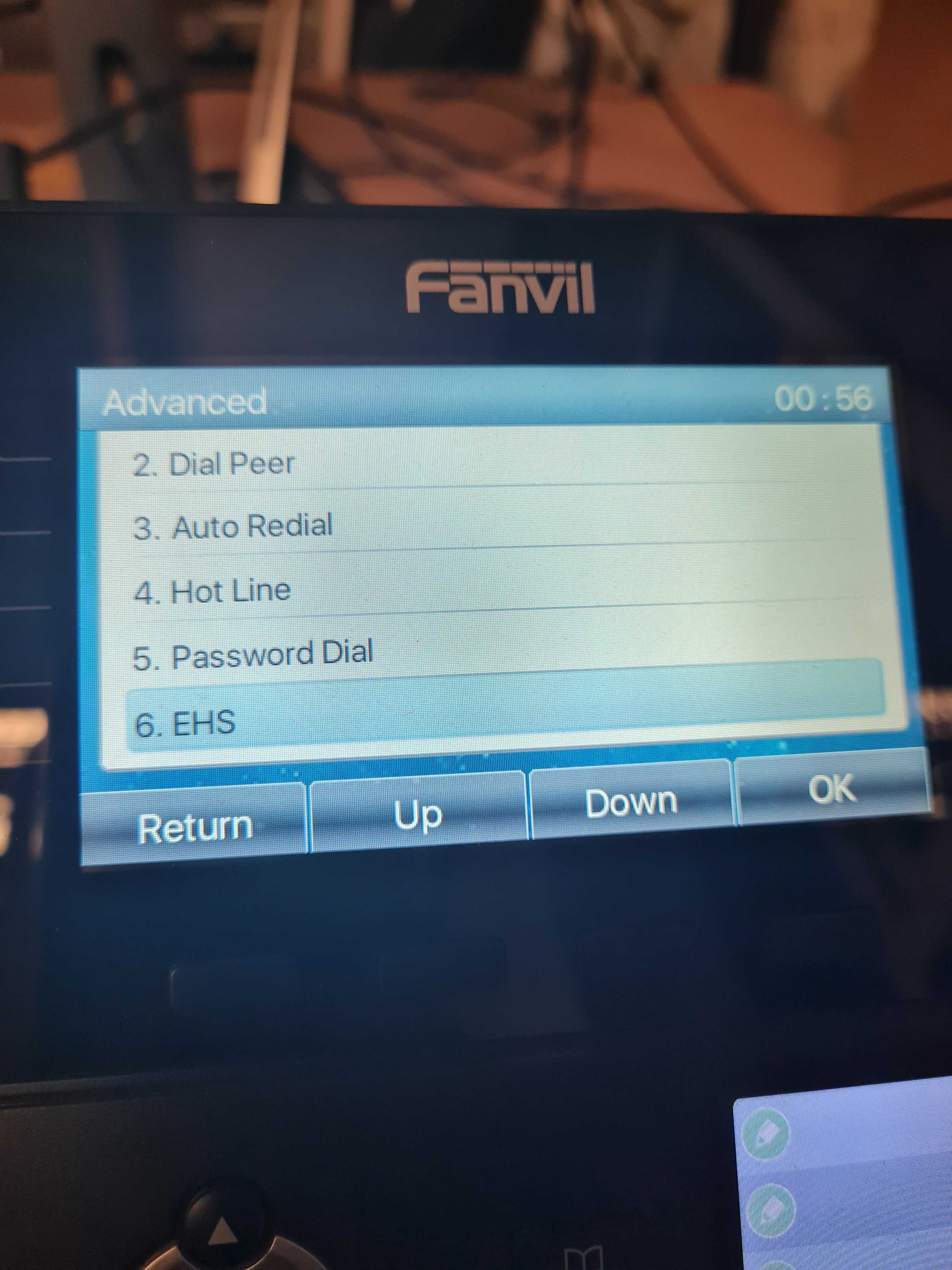
Go to Menu > Features > Advanced > EHS as shown below:
Step 2:
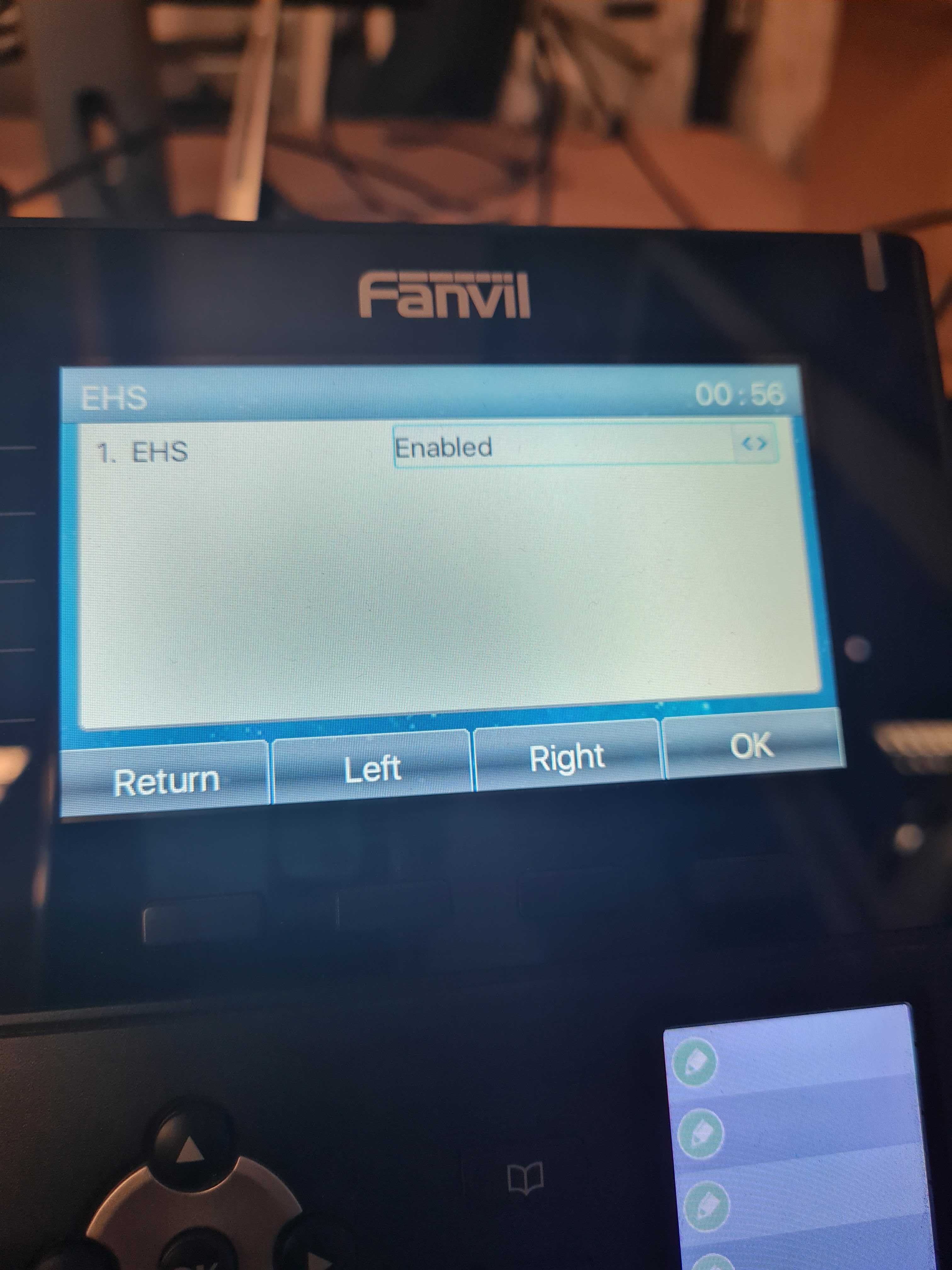
Using the right arrow key set the EHS option to ‘Enabled‘ and press ‘OK‘ to save changes:
Web Interface
Step 1:
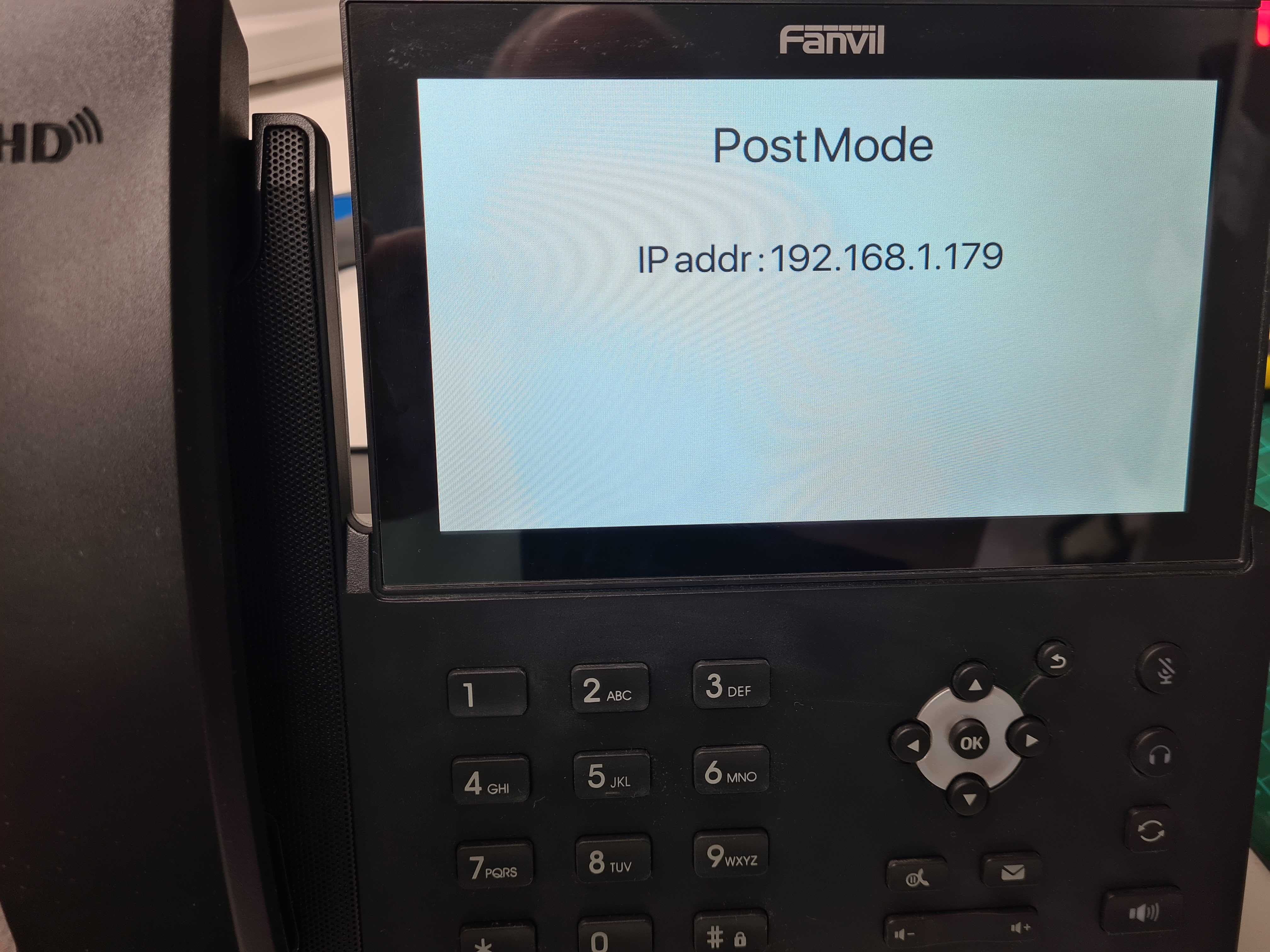
Find the IP address of your Fanvil phone by going to Menu Status or by pressing the ‘OK‘ button.
Step 2:
Once you have obtained the IP address enter this into your web browser you should be then prompted for login credentials, by default these are:
Username = admin
Password = admin
Step 3:
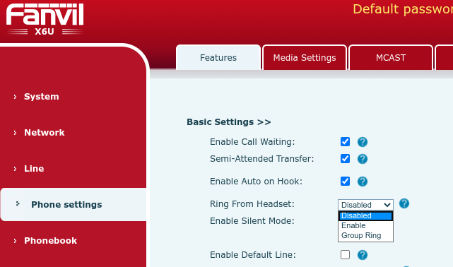
Once successfully logged into the web interface navigate to Phone SettingsFeatures > under Basic settingsEnable a setting called ‘Ring From Headset‘ as shown below:
Step 4:
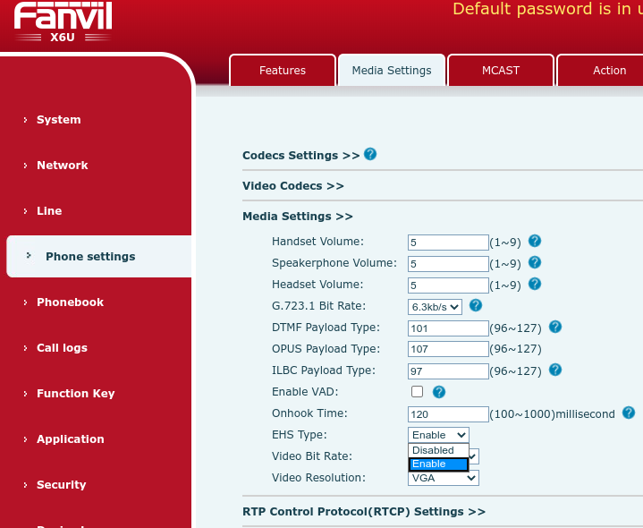
Now go to Media Settings > EHS Type > Enable > finally click Apply.
You should now be able to answer and end calls using your wireless headset.
If you have any problems/issues please contact support@provu.co.uk or call 01484 840048 option 2 for support.
You may be getting reports from your customers saying that when they are on a call, the opposite party is telling them that their audio is too quiet, or maybe even too loud when they talk. Usually this isn’t a problem because the opposite party can adjust the volume of the person calling with their own phone, but what if the opposite party has already done that and it’s still too quiet or too loud?
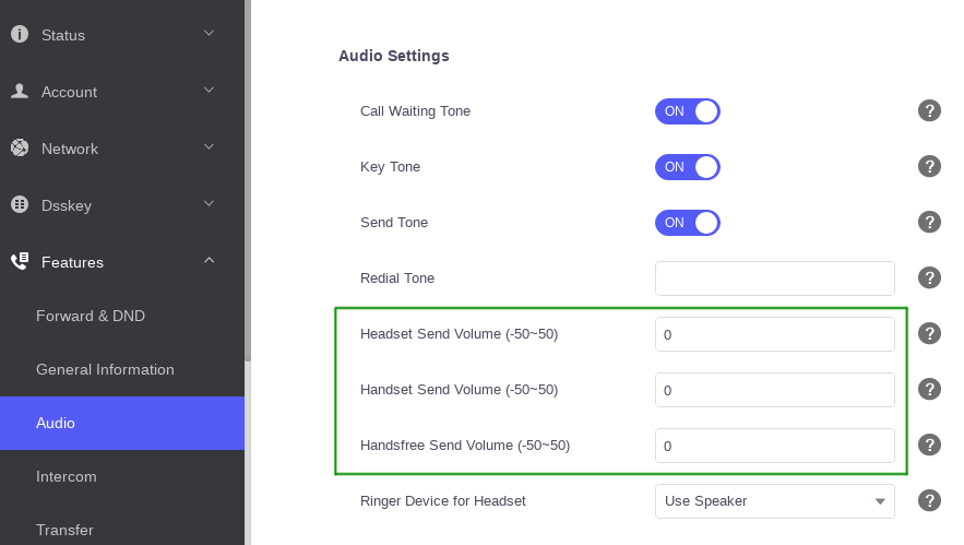
If that is the case then you may be able to adjust three settings on the Yealink device. These can found on the web user interface by going to the ‘Features’ > ‘Audio’ page and adjusting the settings in the image below outlined in green.
An alternative way to think what these settings do is adjusting how sensitive the microphone is on the device. You can adjust the handset, headset and handsfree sensitivity to be weaker or stronger. The valid values are between -50 and 50. The higher the value, the louder it should be. The lower the value, the quieter it should be.
When adjusting this setting it is important to be cautious. Incorrectly configuring the value can have adverse effects on the audio quality so it’s advisable to gradually increase or decrease the value until you find the right spot.
If you control your own provisioning server and would like to configure this remotely you can use the provisioning parameters below:
The aim of this blog post is to provide a guide on configuring the software side of the 2N IP intercom’s to be in a state where they can make and receive calls. It will also detail how to change the door release code and other switch related settings.
This blog post was created with a 2N IP intercom using firmware version ‘2.30.2.39.7’. Previous or future releases may vary slightly.
Prerequisite:
It is advisable to read and fully understand the installation manual for your intercom before proceeding with this guide. The installation manual can be found on the 2N wiki by selecting your model from the listed devices.
Step 1 – Obtaining the IP Address
By default 2N IP Intercom units obtain an IP address via DHCP. There are a few ways to obtain the IP address of 2N intercoms such as the DHCP table on the networks router, alternatively you can use the 2N network scanner, or by pressing certain calling buttons on the intercom just after bootup.
More information can be read about the network scanner, or button sequence on the following 2N FAQ page.
Step 2 – Accessing the web user interface
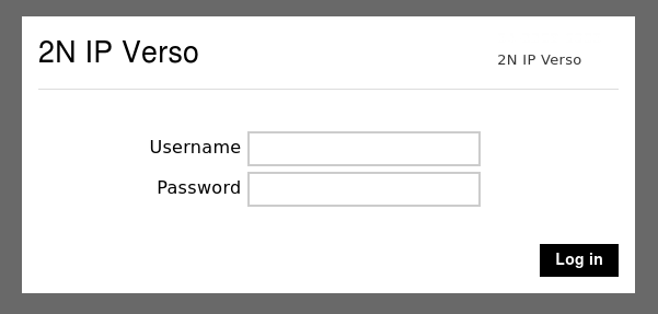
Once you have the IP address of the intercom open your web browser and type the IP address in to the top search bar. Once you press enter it should load the login page as shown in the image below.
The default username is ‘admin‘ and the password is ‘2n‘. If successful it will force you to change your password before proceeding.
Note: Some browsers work better than others, if you have issues with Chrome or Edge, try firefox. You may also see a certificate warning. This is expected behaviour and clicking advanced or proceed should take you to the login page above.
Step 3 – Checking & downloading the latest firmware version
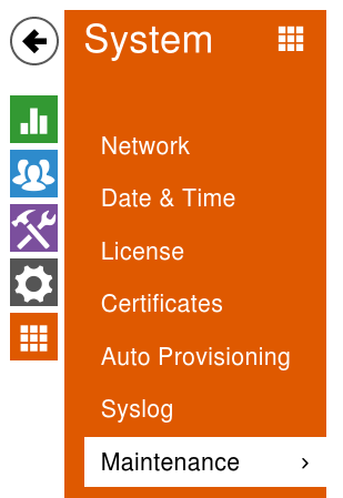
Once you have changed the admin password of the intercom it is advisable to make sure the unit is on the latest firmware version. You can do this easily by going to the ‘Maintenance’ section of the intercom.
To get to the maintenance section of the intercom you can use the ‘Maintenance’ button from the dashboard page
Dashboard Icon
Alternatively click the ‘orange icon’ with 9 squares in it and choose ‘Maintenance’ from the list.
Sub-menu navigation
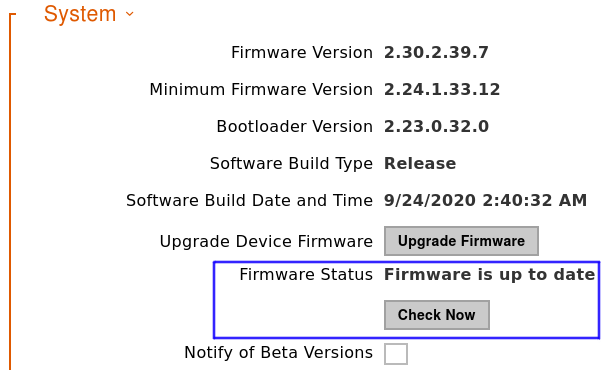
Once on the Maintenance page look for the ‘System‘ section shown in the image below. On this section it may already be reporting that there’s a new firmware version available next to ‘Firmware Status‘. If it doesn’t click the ‘Check Now‘ button.
If it reports a new firmware is available, read the ‘release notes’ carefully and if you are happy click proceed. The intercom will reboot during the upgrade. Once the upgrade is done this section should say the firmware is up to date.
Note: During the firmware upgrade do not remove the device from the network or interrupt the power to the intercom.
Step 4 – Configuring the SIP account & Call behaviour
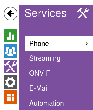
Now the intercom is on the latest firmware version we can proceed to configure the SIP account on to the device. This is done via the ‘Services‘ section and from within here the ‘phone‘ page as shown in the image below.
Sub-menu navigation
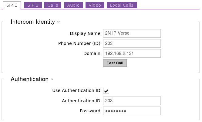
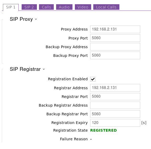
On the phone page it automatically takes you to the tab to configure ‘SIP Account 1‘ but the same applies if you are adding two SIP accounts.
Hopefully you are familiar with applying SIP accounts to VoIP devices and the fields on this page already make sense. If they do, feel free to populate this page and get the SIP account Registered.
If you don’t have much experience and you have taken a hosted seat with an ITSP, and they have provided you with some account settings similar to the ones in the table below, you may not know where they need to go. The right column in the table shows where they would likely go on the 2N intercom.
Details from ITSP
Suggested 2N IP Intercom Fields
SIP Number/Account: 203
Phone Number (ID) field
SIP Password: Password
Password field
SIP Server: 192.168.2.131
Domain, Proxy address and Registrar field.
SIP Port: 5060
Proxy port & Registrar port
SIP Auth: WCXfg453SA
Authentication ID
Note: The SIP Server can be an IP address, but most likely it’s the ITSP domain name.
The SIP Auth is not always provided. If you didn’t get one sent the SIP Auth is usually the same as the SIP Number/Account.
The images below show an example intercom being configured with a SIP account and the Registration status going to REGISTERED. If your Registration status goes to failed and you are sure the details are correct send an email to support@provu.co.uk and we’ll be able to help.
Now hopefully the SIP account is registered successfully with your ITSP or PBX. If it is we can continue with configuring the intercom’s call related settings.
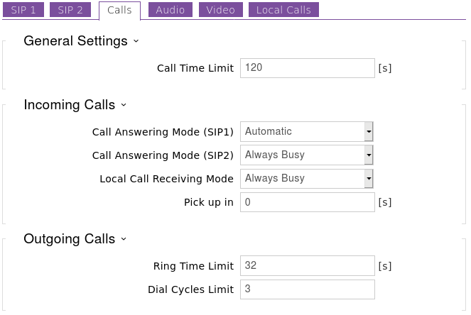
You may want to configure the intercom to automatically answer incoming calls. This is useful for situations where someone maybe stood at the intercom and you want to talk to them without them having to press the calling button. Or this maybe beneficial if you was on a call with someone at the intercom and the call time limit was reached so the intercom disconnected the call.
This behaviour is achieved by changing ‘Call Answering Mode (SIP1)‘ to ‘Automatic‘. When set to ‘always busy‘ the intercom will always decline incoming calls.
Step 5 – Creating users for the Directory, a.k.a – Phonebook
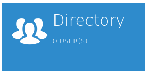
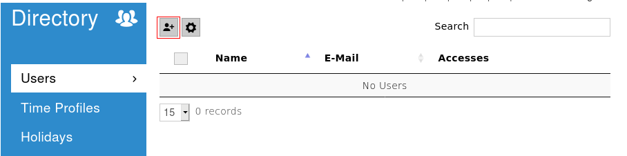
The Directory is where we add users to the intercom and also configure unique/personal details for them such as an RFID keyfob or a Name and number which is what we are going to look at.
From the main dashboard click the icon below to get to the directory.
Dashboard Icon
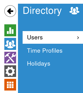
Or alternatively from the sub-menu navigation go to the section shown in the image below.
Sub-menu Navigation
Once your on this page, to add a new user entry click the icon of a person as shown in the image below highlighted by the red box.
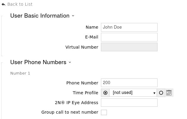
Once you click that button it will take you to a page asking for the Name, Email address, User phone numbers and user specific access settings. In this guide we’re just going to do the Name and Numbers. If this person has more than one number, add them in to the available number fields. If you want all three numbers to ring at the same time select the ‘group call to next number‘ and click ‘save‘ at the bottom of the page.
Example below:
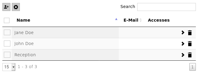
Repeat the above step for the desired amount of users. Once you’ve added some more users you should end up with a list when you go to the directory page.
Step 6 – Configuring the dialling buttons
This is the step where we program the calling button with the users to call. The system doesn’t automatically add the users because it may not be desirable to call every user.
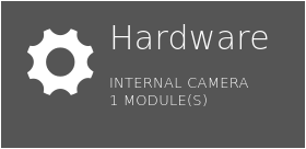
You can get to this section by pressing the Hardware icon on the dashboard.
Dashboard Icon
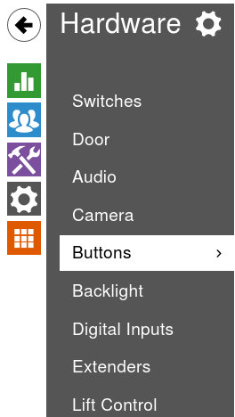
Or you can use the sub-menu navigation as shown in the image below:
Sub-menu Navigation
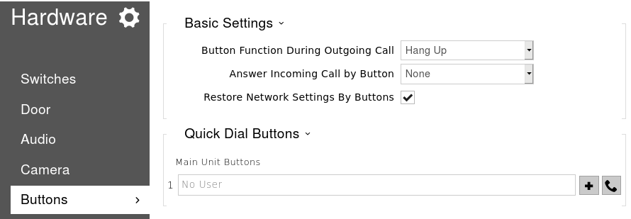
Once you are on the ‘Buttons’ page you will see that there are no users added to the main button. To add a user you need to click the ‘+‘ symbol next to the empty field.
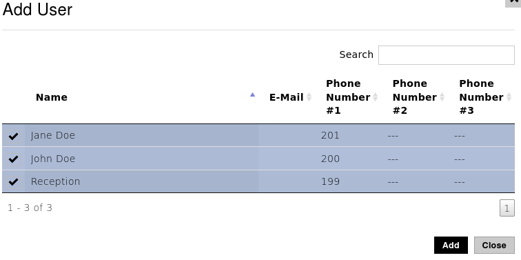
Once you click the ‘+‘ symbol it should bring up a new page with a list of the users from the directory, find the users you want to call, select them and click the add button. Example Image Below:
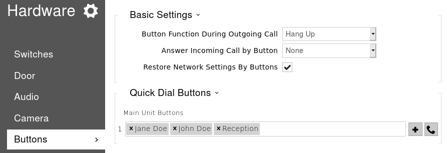
Once you’ve clicked add you should see the users appear against the main unit button. If you are happy with this click the ‘Save‘ button at the bottom of the page.
Now when the button on the intercom is pressed it should dial the programmed numbers via the SIP account configured in step 4.
A Handy tip, if the intercom isn’t nearby, to save yourself a walk you can click the ‘handset’ icon next to the assign user button to simulate a button press. (hopefully your near the phones to answer or hear them ringing).
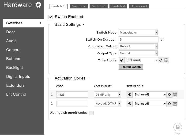
Step 7 – Configuring the switch & activation code
The final step in this configuration guide is to edit the switch activation code and change some other settings that maybe relevant to your deployment. The default activation code is ’00*’ but it’s highly recommended to change this to something else.
To do this we need to get to the ‘Switches‘ page and we can do this straight from the ‘Button’ page by clicking ‘Switches‘ at the top. Once on this page we can change the switch code under ‘Activation Codes‘.
As the image shows above you can apply two switch codes to each switch but usually one is enough. In the image above I have changed the switch code to 4325. Notice that I didn’t defined the ‘*’ which is be required when entering the code via DTMF (During a phone call).
If desired you can set it so the intercom doesn’t require the ‘*’ to be entered for confirmation by clicking the ‘Advanced’ tab at the top of the page and enabling legacy switch code.
Legacy switch code is only applicable for switch code 1.
Depending on your installation you may also need to change the settings in the table below:
Switch Setting
Description of Setting
Switch-on duration
Defines how long the switch will remain active in monostable mode. i.e – How long will the lock be released.
Controlled Output
Defines which output is used for this switch when activated.
If you’ve connected a lock to the ‘relay‘ on the PCB, select this.
If you’ve connected the lock to the ‘output‘ on the PCB use this.
Output Type
The type of lock being used will change which value needs to be applied.
‘Normal‘ is usually for a fail-secure lock, ‘Inverted‘ is usually for a fail-safe lock. ‘Security‘ is only applicable if the 2N security relay is being used.
To test your switch is working, you can click the ‘Test the switch‘ button on this page. If that works the setup is done. All you need to do now is make sure the intercom is working as expected.
Of course this is just a very basic guide covering the first steps on every intercom, if there are some additional requirements for the customer, or if your having issues with one of the stages above just send an email to: support@provu.co.uk
Also a very good place for 2N resources is the 2N Wiki and FAQ.
This blog post is going to outline the steps to take to source the required file. If you contact the ProVu support team experiencing Registration or Call issues with the Cisco CP series of phones, we will require a PCAP trace capturing the problem to help identify the cause of the issue.
Step 1 – Access the web user interface
In order to access the web user interface of your device you will need to find the IP address. There are a few ways this can be done such as logging in to your router and checking the DHCP table, but most likely the easiest method and the one this blog post is going to cover is to get it physically from the phone.
You’ll need to press the ‘Settings‘ button on the phone which has the symbol of a cog. Once you have pressed this button scroll through the options available and select ‘Status‘ > ‘Network Status‘ > ‘IPV4 Status‘ and make a note of the IP address.
Once you have the IP address, open a web browser and type the IP address in to the top search bar and press enter as displayed in the image below.
Once you have pressed enter it should take you to the ‘Info‘ page. On here you need to select the admin user and then advanced options by clicking the red outlined text in the image below.
(By default there is no admin password applied but if you have set one it will require this)
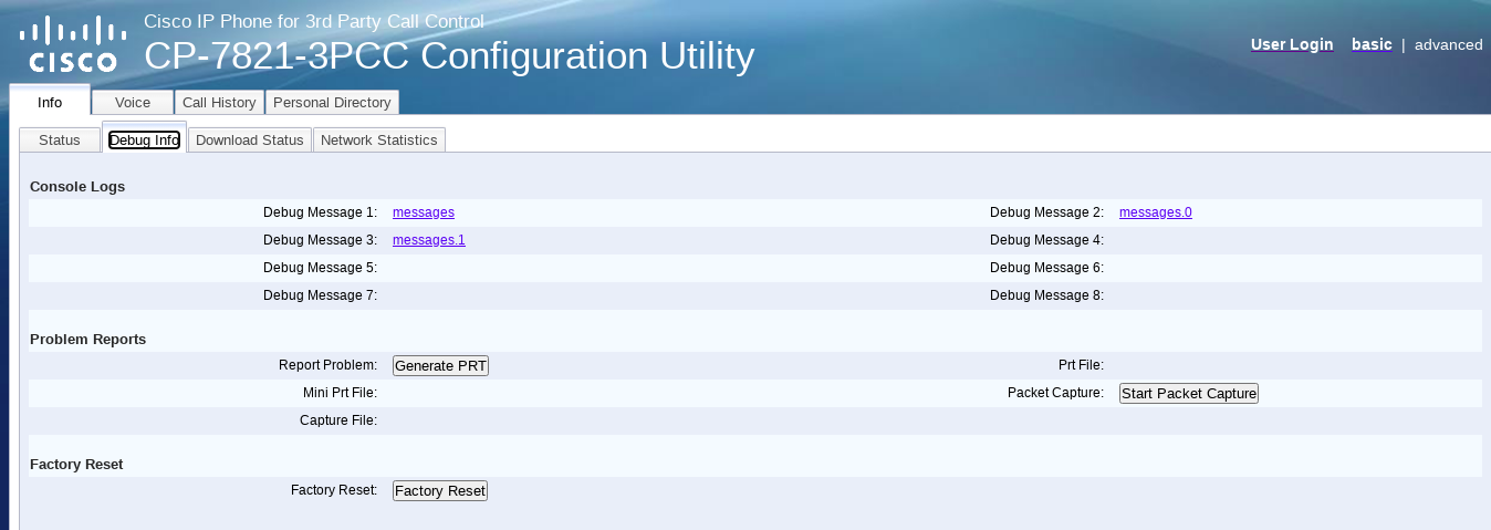
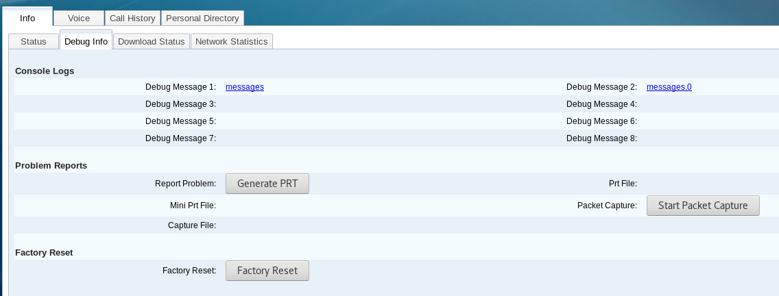
Once you have done that go to ‘Info‘ > ‘Debug Info‘ and you should be on the page below.
Step 2 – Capturing the ‘.pcap’ trace
On the ‘Info‘ > ‘Debug Info‘ page there is a section under ‘Problem Reports‘ that says “Packet Capture” with a button next to it. Follow the steps below to generate the file.
Press ‘Start Packet Capture‘ and select the capture filter to ‘All‘.
Replicate the issue – if your issue is related to outbound calls failing, attempt to place an outbound call. If your issue is related to Registration issues you can force a Registration by disabling and enabling the SIP Account:
To do this you need to go to ‘Voice’ > ‘Ext 1‘ and change ‘Line Enabled‘ to ‘No‘. Then click ‘Submit all Changes‘ at the bottom of the page. Wait 30 seconds for the web user interface to reload and then go back to ‘Voice‘ > ‘Ext 1‘ tab and change ‘Line Enable‘ to ‘Yes‘ and click ‘Submit all changes‘.
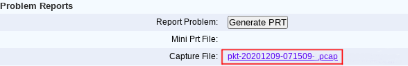
Press the button next to ‘Packet Capture‘ again (this time it should say “Stop Packet Capture“)
Once the trace has been stopped and generated you can download it from “Capture File” link outlined in the image below.
Once you have download the file please send it to the engineer requesting it, or to support@provu.co.uk if this is the first time reporting the issue.
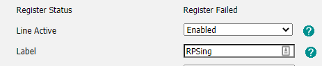
If you have recently factory reset a Yealink handset then you may see the following notifications on your devices screen. ‘input sn‘ on the first line (top left of the screen) or ‘RPSing’ on the account information on the web interface.
In this blog, we will take you through a few short steps you can take to solve this issue and have your phones back up and running as soon as possible.
Step 1:
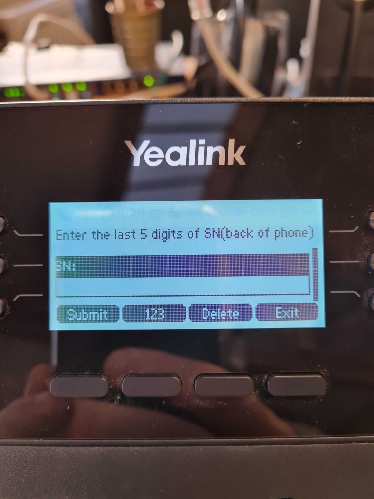
Click on the function key where ‘input sn‘ is located. You should then be presented with the following page:
Enter the last 5 digits of the serial number (Not the MAC address)
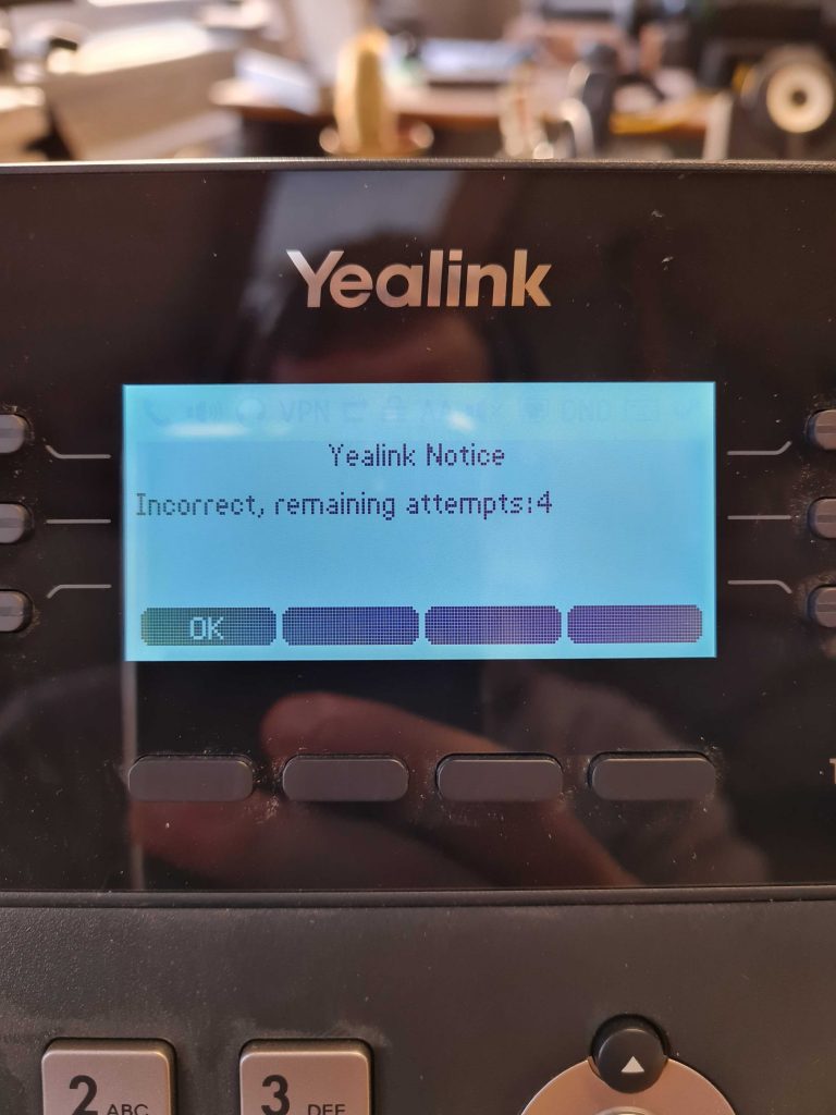
You get x5 attempts at entering the correct SN, if you enter the incorrect serial number you will get the following message:
Step 2:
Once you have entered the last 5 digits of the serial number the phone should then reset and boot up as normal.
Entering the serial number bounds the phone onto the Yealink RPS account.
If you run into any issues or would like more Yealink technical advice, please contact support@provu.co.uk or call 01484 840048 option 2.
We have been getting a few reports of users who have been using the Bria Enterprise application without any issues. However, once the iOS device is upgraded to version 14, users have been experiencing 503 and 408 errors relating to the SIP account registering.
This appears to be due to an iOS setting and not the Bria application. If you are experiencing this issue please check that ‘Local Network’ has been enabled. This can be checked on the iOS device by going to:
Settings > Privacy > Local Network > Enable
If you are still experiencing issues after enabling this setting. Please proceed to generate an application support log as shown in this blog post.
You may have recently noticed that some of your Yealink T2x & T4x series devices in use on your 3CX platform have been telling you that the FW version is no longer supported and you need to upgrade.
Yet when you try and upgrade using the 3CX fw upgrade feature it fails. The phone appears to start the upgrade but then reboots and does not upgrade.
The problem specifically is an earlier FW version that users were prompted to upgrade to.
The version in question is xx.83.0.55.
Something broke FW upgrading in this version and phones that found themselves on this version are no longer able to upgrade directly to the latest recommended 3CX FW version.
The fix for this is to manually upgrade the phones to an intermediary version xx.84.0.35 that fixes the FW upgrade issue.
Worth noting that it should also be possible to provision this upgrade to the phones.
After this upgrade the phones will be able to upgrade normally using the 3CX platform.
Helpfully, 3CX have published some guides on how to do this and where you can find the required FW files.
If for any reason you are unable to perform this upgrade manually, let us know, and we may be able to assist you in provisioning this upgrade to your devices.
Part 1 – Configure the unit to start logging in ‘DEBUG’ mode and replicate the issue
Login to the web user interface and select the ‘admin‘ user. After selecting the ‘admin‘ user go in to advanced mode by pressing ‘advanced‘ on the top right of the screen.
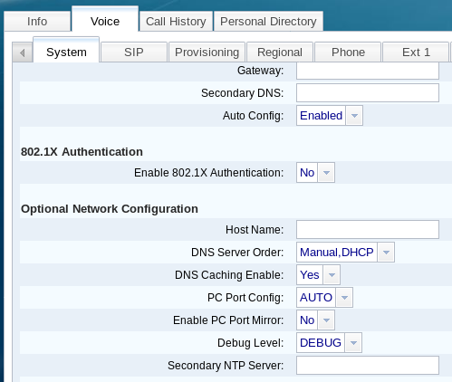
Once ‘advanced‘ mode is applied press the ‘voice‘ tab and also the ‘system‘ tab. Once on the ‘system‘ page scroll down until you get to ‘Optional Network Configuration‘ and in the drop down box next to ‘Debug Level‘ set this to ‘DEBUG‘ and press ‘Submit All Changes‘.
Now that the phone is logging everything in ‘DEBUG‘ mode you need to replicate the issue.
Part 2 – Generating the log
Now the you’ve replicated the issue we need to export the log.
To do this follow the steps below:
Login to the web user interface as before using ‘admin‘ and ‘advanced‘ mode. Once logged in select the ‘info‘ tab and also the ‘Debug Info‘ tab. Once you are on this page press the ‘Generate PRT‘ button.
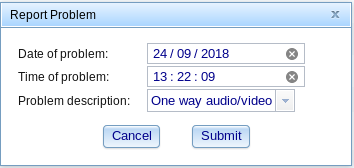
Once you press the button you will get a popup box asking you to enter the date and time of the problem as well as selecting a description. If your problem isn’t listed select ‘Other‘ and press ‘Submit‘.
After pressing ‘Submit‘ and allowing the phone to generate the file you should get another popup notification saying the PRT file has been generated and can be access from the phone directly. Press ‘OK‘ and download the file by clicking on the PRT file link across from the ‘Generate PRT‘ button.