You are out of the office and only have access to E-mails but you still want to be notified when someone is at the front door. Creating this simple automation will allow you to receive an E-mail with the time and date of when someone presses the button on the 2N Verso. You can also get it to send you a picture of who it is that pressed the button.
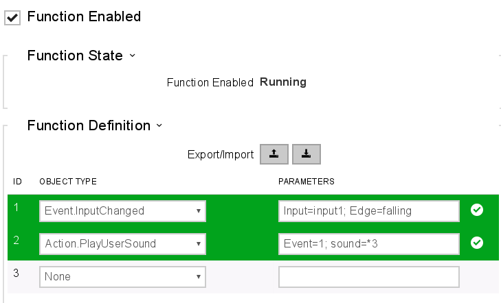
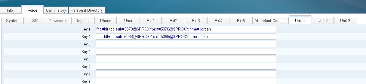
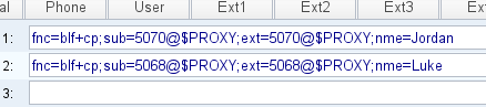
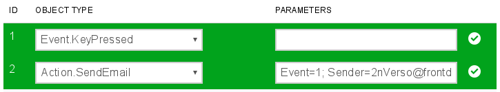
Go on the 2N web-interface and go to Services (Purple tile) > Automation, from this page you will need to tick the box “Function Enabled” and fill in the “Object Type” and “Parameters” as seen below:
Event=1; Sender=2nVerso@frontdoor.com; Email=YourEmailAdress; Subject=Someone has tried calling you; (Subject can be changed to say what you want)
Go to the “E-Mail” tab, this is were you will need to put your smtp server address along with your email address and password. If you are using your gmail account then the smtp server and port are most likely going to be as follows:
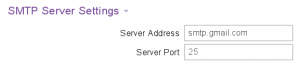
For more information about the smtp server settings go to this page: https://wiki.2n.cz/hip/conf/latest/en/5-konfigurace-interkomu/5-4-sluzby/5-4-4-e-mail
You have now finished, you can now test this feature by pressing the intercom button and watch your inbox for the email to come through, as shown below: 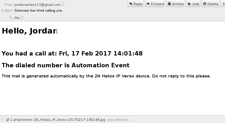
If you have any issue please contact our support team.