Browse Author

Paul Hayes

Installing Sangoma cards with Asterisk and Dahdi on Debian Wheezy

My preferred method for installing Asterisk on Debian is by using standard Debian packages. I don’t want the hassle of re-compiling packages whenever there is an updated version or some security hole gets closed.

Step one is getting Asterisk & Dahdi installed and working.

Do this:

apt-get install asterisk libpri1.4 asterisk-dahdi

The country code for the UK is 44.

Now to get the dahdi kernel modules built, install dahdi-source and use module assistant to install the modules:

apt-get install dahdi-source

m-a a-i dahdi

Now you should have Asterisk & Dahdi installed.

Before installing the Sangoma Wanpipe drivers, you need to compile the Dahdi source (module assistant just compiles the kernel module parts):

cd /usr/src/modules/dahdi

make

The rest is the same as the standard installation instructions for Wanpipe which are here (scroll down to Sangoma Driver Installation):

http://wiki.sangoma.com/wanpipe-linux-asterisk-dahdi

In summary:

apt-get install automake autoconf libtool libncurses5-dev bison libxml2-dev cmake flex

wget ftp://ftp.sangoma.com/linux/current_wanpipe/wanpipe-current.tgz

tar xzf wanpipe-current.tgz

cd wanpipe-{version}/

./Setup install

and just follow the instructions.

Paul Hayes.

RTX4002 DECT Repeater beeping

If you find that when using an RTX4002 DECT repeater (with any device such as Gigaset) and you are hearing beeps on the phone then you will have inadvertently turned on the “verification tone”.

The idea of this is so you know when the repeater is being used but the procedure to turn it on is very similar to putting the device into Registration mode so it’s easily done by mistake.

To turn it off (or on for that matter), do this:

– switch off the unit (disconnect the power supply)
– switch on for 1-5 seconds and switch it off again
– switch on again. When the LED of the unit starts to flash slowly, switch it off again
– switch it on again. The verification tone will then be turned on or off (depending on whether it was on or off before).

Panasonic products win awards from TMC in America

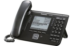
Panasonic SIP phones have won several awards from the TMC Labs media outlet in the USA.

First off, the KX-UT670 Android based media phone was given an exceptional innovation award.

Read the full press release on the Panasonic website

More info on the KX-UT670

If that wasn’t enough, the KX-UT248 also won the 2012 Internet Telephony (an industry magazine in the USA, published by TMC) Product of the Year Award.

Read the full article on the TMC website.

More info on the KX-UT248

So well done to Panasonic for making such an impact on their first foray in the SIP phone market.

ProVu have been the distributor for the phones in the UK for most of 2012 and have as usual, developed support for them in our phone provisioning and management systems.

Siemens Gigaset – IP DECT Transfer ‘How To’

There are two types of transfer on a Gigaset IP DECT phone. The first way is called a DECT transfer and can only be used to transfer a call to another handset registered to the same base station.

The second type is a SIP transfer and can be used to transfer a call to any other number using your VoIP service provider or PBX. Chances are this is the type of transfer you want to do so you can skip right to the SIP transfer section if you want to.

Please note that you cannot transfer analogue/PSTN call to an external pstn number.

DECT/Internal Transfer How-To

  • During a call, press the “int” key on the handset. This is usually the left hand button on the four way navigation key in the middle but it depends on the handset model.
  • The person you were talking to now hears some awful music on hold generated by the Gigaset phone itself! which can be turned off from the web interface.
  • You will see a list of the other DECT devices registered to the base station, select one of the the dect handset and press the green dial button and it will start ring.
  • Announce the call and press the Red hangup key when ready to transfer.
SIP/External Transfer How-To

An external transfer is made a lot easier if you change a setting in the web interface of the phone before hand. You only need to do this once by the way!

There are two settings to look at. First setting is called "Transfer Call by On-Hook" and is found by clicking "settings" then "telephony" and "advanced" in the web interface. Change it to "yes". Other settings is " Use the R key to initiate call transfer" and found on the same page, change it t "yes"

After this the actual transfer process is fairly straight forward:

  • During a call, press the R keys on the handset which can be found on the lower left or right side of the keypad
  • Dial a number and press the green button to make a call.
  • When you are ready to transfer, simply press the hang up key on the Gigaset handset and the other two callers are connected.

Very secure Yealink provisioning coming soon

Just a quick note to say that I was supplied a specially modified version of a Yealink T28P a few weeks ago which has HTTPS certificates loaded into it.

There are two certificate chains, one is used by the provisioning server to verify the identity of the phone. The other is used by the phone to verify the identity of the server. There is a list of a few popular certificate signing authorities you can buy a certificate from for the server identity.

This two way identification is what is required for a truely secure provisioning system. It protects against attackers attempting to obtain SIP configuration from our servers and protects against DNS spoofing/poisoning attacks against your phones.

We sometimes get asked for HTTPS provisioning and of course it is pretty simple to implement. But without these certificates it is fairly useless. It does nothing to guarantee the identity of the server or the client.

At the moment this is a Beta test, we will be rolling out this provisioning option as soon as we can, in the next few weeks. It requires Yealink to start supplying phones with certificates pre-loaded at the factory and requires a certain (currently test-only) firmware version.

If any of this is of interest, please let us know.

Raspberry Pi and Asterisk

Asterisk running on Raspberry Pi

I’ve been playing around with a Raspberry Pi for a few weeks now and thought I’d see how well Asterisk Open Source PBX works on it.

<%ThickBox(http://blog.provu.co.uk/media/4/20120618-raspi.jpg|Raspberry Pi)%>Raspberry Pi running on my desk

I’ve tried a couple of different versions of Debian on this device and have settled with Raspbian since this makes use of the floating point co-processor that is emulated in the normal Debian Armel packages. It’s early days for Raspbian yet and all the Debian packages have to be re-compiled but most stuff seems to be done and it works very well. Raspbian should perform better for tasks relying on the not-very-powerful ARM11 CPU on the Raspberry Pi.

As for Asterisk, proper Debian packages already exist for the Armel compiled operating system and it is simply a case of running “apt-get install asterisk” on the Raspberry Pi and it installs and works.

At the moment there is no package for Raspbian and also, I wanted to try out Asterisk 10. So I compiled from source.

The steps I took were:

  • Download the source from the Asterisk website, extract the tar archive
  • I started from the “hexxeh” Raspbian image which can be found on the Raspbian website. This already comes with most tools needed to build software, if you have installed from somewhere else just make sure you have got the build-essential Debian package
  • You will also need to install these packages: libncurses5-dev, libsqlite3-dev, libssl-dev (or chan_sip will be automatically unselected, this isn’t needed if you don’t want SIP)
  • Possibly more packages if using a different image of Raspbian or you’ve built your own.
  • Now back in the Asterisk 10 source folder you just extracted, issue the command “./configure –disable-xmldoc”. The option is to allow it to continue without installing the libxml2 development package
  • Now before running the build, it’s a good idea to check the modules you need will actually be built, the command: “make menuselect” will bring up a text menu that allows you to check the modules. In particular make sure chan_sip in the channels section is selected!
  • After that simply run: “make”. This will now compile Asterisk and all the modules you’ve selected. This will take around an hour on the Raspberry Pi native hardware! Note: you can use a cross compiler on more powerful hardware to build packages much quicker.
  • Now run: “make install” which will install the compiled software
    • <%ThickBox(http://blog.provu.co.uk/media/4/20120618-raspbian_asterisk.png|Asterisk 10 running)%>Asterisk 10 running

      Now you have installed Asterisk, you can run “make samples” to generate sample Asterisk config or write your own.

      So how well does it work?
      Surprisingly well I thought for a CPU that is generally thought to be approximately equivalent to a Pentium II 300 MHz. I have not done serious load testing but I set up a conference bridge (using the new confbridge feature in Asterisk 10) and it very easily handled 4 local SIP extensions in a conference at once. It’ll be interesting to see how much transcoding it can handle.

      This doesn’t mean that we’re going to start selling IP-PBX based on the Raspberry Pi. The hardware is still a bit too new and untested for the time being and the software is still very much in development. The main reason though is that for low-end hardware to run a PBX off, things like Sheevaplug make more sense. This has a more powerful CPU, more memory and by the time you factor in storage, power & casing for the Raspberry Pi, a Sheevaplug isn’t much more expensive.

      The Raspberry Pi’s CPU is a couple of generations out of date ARM11 core with ARMv6 instruction set. Where the devices shines is the GPU attached to it. This is a Broadcom VideoCore GPU and is pretty impressive indeed. It’s intense graphical processing that the Pi does best, that fact it can decode 1080p30 h264 “HD” video is very impressive (and I have tested this too).

      So while it runs Asterisk quite nicely for just a few phones not doing very much, it seems a bit of a waste to use the Pi for this since it’s not using it’s powerful graphics engine at all. I need to think of some graphical uses for it! Perhaps a fancy OpenGL-ES based call centre wall board system.

Sangoma Vega 100 as an ISDN gateway to a SIP PBX

The aim is to use a Sangoma Vega 100 single port PRI gateway as an ISDN gateway for a SIP PBX.

All the Vega will do is forward anything it gets on the ISDN line to the SIP PBX and forward anything from the SIP PBX to the ISDN line.

Steps as follows:

  • Web browse to the Vega and login
  • Go to the Quick Config section
  • On the E1/T1 page, change the number for Interface 1 to just “.*” (dot-star without the quotes)
  • Ignore lines 2-4
  • Open up the Port Settings (ISDN line settings) section and check that the line is set to the correct mode, TE (not NT)
  • On the SIP tab, enter the IP or hostname of your SIP PBX into the domain and proxy settings. You do not need Outbound Proxy and it’s best to set this up without Registration
  • Apply the quick config

That should be it, the Vega will forward SIP to ISDN and ISDN to SIP regardless of numbers received on either side.

The main settings for this are in “Dial plan” in Expert Config. You can see what has been generated in the “To_SIP” and “To_E1T1” dial plans.

Note: this should also work on Vega 200 and Vega 400 if you add the other ISDN interfaces into the planner group that the dial plan “To_E1T1” uses.

Panasonic factory reset

To do a proper factory reset of a Panasonic SIP phone you need to have the phone in front of you.

There is a reset option in the web interface but this will only reset any settings that had been set in the web interface itself. Any settings that have been provisioned will persist.

On the phone:

  • Press the “setting” button to go into the settings menu
  • Dial: #136 on the keypad
  • A hidden menu will appear, select “Factory Reset”
  • Press up or down to choose “yes” and then Enter
  • Repeat the previous step for the “are you sure” prompt
  • The phone will now reboot itself

Once rebooted, it’ll be fully reset. Just be aware, if the phone has been provisioned it may well call home to the provisioning server and get some settings applied from that. You’ll have to speak to whoever does your provisioning for us (hopefully us!).

cheers,
Paul.

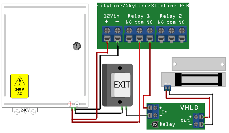
Door entry wiring diagram 2 – fail safe, high power magnetic lock with CityLine/SkyLine/SlimLine

This connection diagram shows how to wire up a high-power (more than 350mA) electronic door lock using an external power supply with any of the CityLine, SkyLine or SlimLine range of door entry devices.

CityLine info.

SkyLine info.

SlimLine info.

Wiring Diagram

Parts Required

These can all be bought from ProVu.

    • Any ProTalk CityLine, Skyline or SlimLine IP door entry kit


    • 240Volt AC mains to 12Volt DC power supply (with internal battery back up highly recommended)


    • A 12Volt “fail-safe” door lock – large magnetic lock shown in diagram


    • A “push to break” exit switch


    • “VHLD” – Very Handy Little Delay


Notes

    • Mains voltage is dangerous! If you aren’t 100% confident you know what you are doing, hire a qualified electrician (at least for the power supply installation)


    • This set up is intended for use when you have large locks that require more than 350mA current or as a way of adding battery back up


    • Whilst the door entry unit itself can be powered from PoE, it makes sense to use the same 12V power supply since it is installed and (hopefully) battery backed


    • Make sure the power supply is more than capable of supplying enough power for both the lock(s) and the door entry unit


Door entry wiring diagram 1 – fail safe, low power, strike plate with CityLine/Skyline

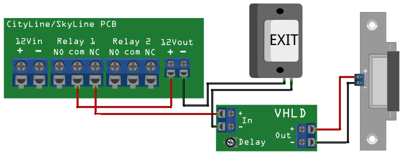
This connection diagram shows how to connect a electronic door strike plate up to any of the CityLine or SkyLine IP door entry units we sell.

CityLine info.

SkyLine info.

Wiring Diagram


Parts required

These can all be bought from ProVu

    • Any ProTalk CityLine or SkyLine IP door entry kit


    • A 12Volt “fail-safe” electronic door strike (max 350mA)


    • A “push to break” exit switch


    • “VHLD” – Very Handy Little Delay board


Notes

  • Ensure the exit switch is push-to-break, not push-to-make, or this will not work
  • If an emergency break glass is needed, connect this in series with the normal exit switch
  • The Door Entry unit cannot supply more than 350mA from the 12Vout connector, do not attempt to use a door lock which will draw more power or you will damage the door entry unit (and void the warranty!). If you have a more powerful door lock then a separate power supply must be used (which I’ll draw a diagram for soon).
  • 12Vin is not shown connected as you can power the whole device & circuit from either this or Power-over-Ethernet.
  • You can adjust the amount of time the door is unlocked for by setting the “delay” potentiometer on the VHLD board, anti-clockwise increases the delay.

I will be drawing a series of these diagrams to suit various scenarios so keep checking here for more.