Browse Category

Technical Hints

How to put RTX 8630 base in to multi-cell mode

1) Find the IP address of the base unit and enter that in to a web browser to configure the device.

2) Once you have logged in (Default username and password are both admin) go to “Time” on the left hand column and enter a timeserver in the field. Once you have done this click save and reboot. (a reboot is required to work correctly)

3) Now go to “Servers” (This is where we configure the PBX details and tell the extensions where to register). Enter the relevant information in to the fields and then click save.

4) Next go to “Extensions”, click “add extension” and fill in the relevant information for the extension such as authentication name and password. Don’t forget to choose the server we created otherwise the extension will not register.

5) Next go to “Multi cell” and change “Multi cell system” to “Enabled”, then create a “system chain ID” all the bases that are going to be paired need to have the same ID number. The Synchronization time can be increased/decreased to change how often the bases sync together. Leave “Multi cell debug” set to “None” for general use (only change when you need to debug issues) then click save and reboot.

Once the base has rebooted on the “Home/Status” page it should come online as Multi cell Unchained(Unchained) Allowed to Join as Primary

6) Connect the second base and follow step 1, 2, 5. (Repeat for every base being connected)

7) Once the second base has rebooted, on the “Home/Status” page  it should come online as Multi cell Unchained(Unchained) Allowed to Join as Secondary. Wait a few minuets and let the bases communicate with each other.

8) On both bases it should now look different under “Multi Cell”. The base with the extension should be listed as the “primary” and the other base/s should be “locked” under “DECT property”.

Please note: if your base has been displaying (UnchainedAllowed to Join as Secondary) for a while make sure you have created at least 1 extension on the primary base.

How to configure BLF keys on Cisco CP-7800/8800 series

To set up BLF keys, first go onto the web interface. Then go to Admin Login > Advanced.    admin

Then go to Voice > Phone.

voice


You should then have all the line settings.


To set up a BLF key you must first know which extension you want the button to call. For example I am going to use 1001. Where it says the extension number you must select the option ‘Disabled’.


disabled

Next you must add the BLF syntax to ‘Extended Function’. Which in this case would be ‘fnc=blf+sd;sub=1001@$PROXY;ext=1001@$PROXY’.

‘sub=1001’ is the number which you are subscribing to. ‘ext=1001’ is the extension number. ‘@$PROXY’ tells the phone to subscribe using the sip server of the extension that is registered on the phone.

So in order to make it function all you need to do is change the subscriber ID and extension ID to match the phone you want it to ring.


How to set up Email notification from 2N movement detection

In case you didn’t know there is a feature on the 2N verso that allows you to receive an email notification that tells you when the camera has detected motion – This feature requires a gold or enhanced integration licence.

The camera on the verso will take screen shots of the object that has triggered the motion detection and attaches them to the email that the verso sends to you.

To do this, Go to “Services” (Purple Tile) > “Automation” and fill in the “Function Definition” with the following information below:

screenshot-from-2016-11-14-110450


Event.motionDetected and Condition.True you do not need a parameter (Condition.True is optional), the parameter for Action.SendEmail is: Event=1; Sender=2nVerso@frontdoor.com; Email=youremail@hotmail.co.uk; Subject=Motion has been detected; Body=Movement has been detected by the 2N Verso, see the following snapshot; Snapshots=1; Width=640; Height=480  (you can change the subject and the body to what you want your email to say)

Go to the “E-Mail” tab, this is were you will need to put your smtp server address along with your email address and password. If you are using your gmail account then the smtp server and port are most likely going to be as follows:

screenshot-from-2016-11-14-113436

For more information about the smtp server settings go to this page: https://wiki.2n.cz/hip/conf/latest/en/5-konfigurace-interkomu/5-4-sluzby/5-4-4-e-mail

The last step is to go to “Hardware” (Grey Tile) > “Camera” > Internal Camera tab at the top and then Enable “Motion Detection”

screenshot-from-2016-11-14-114438

You have now successfully set up Email notification from 2N movement detection, now when an object or a person passes in front of the camera you will get an email that looks like this:

screenshot-from-2016-11-14-114831

If you are still having problems please contact our support team.

Configuring the 2N Helios IP Uni with Panasonic KX-HDV130 with peer-to-peer dialling

We have recently been testing the 2N Helios IP Uni with the Panasonic KX-HDV130 entry level handset via peer-to-peer calling. After some very straight forward testing, we managed to get it working. You may use this scenario if you don’t want to involve an IP PBX.

Please note that this guide applies to the 2N IP range.

2N Helios IP Uni Configuration:

You will need to web browse to the IP address of the 2N Helios IP Uni which can be done by powering the unit via a Cat5e cable, then pressing the button on the unit five times once you have heard the initial startup tone. Then unit should then speak out the IP address of the unit to you.

Once you have obtained the IP address of the device, you will need to web browse to the IP address of the device e.g. ‘192.168.x.xx’. The default username is ‘Admin’ and the default password is ‘2N’. It is highly recommended that you change the default password before you start using the device.

Once you have logged into the web interface of the IP Uni, you will need to navigate to ‘Directory’ (blue tab), then make sure that the ‘Position Enabled’ field has a check in the box, then enter a relevant name in the ‘Name’ field under ‘User Basic Information’. Finally, you will need to enter the IP address of the Panasonic KX-HDV130. You can find out the IP address of the KX-HDV130 by navigating to ‘Menu’, ‘System Settings’, ‘Status’, ‘IPv4 Settings’, then ‘IP Address’ on the phone. The IP address should then be displayed on screen e.g. ‘192.168.x.xx’. The IP address should look something similar to ‘192.168.x.xx’ which needs to be inputted into the ‘Phone Number’ field under ‘User Phone Numbers’. It is important to make sure that you have included ‘sip:’ before inputting the IP address e.g. ‘sip:192.168.x.xx’. You will then need to apply the changes to the unit by clicking the ‘Apply’ button located at the bottom right hand side of the interface.

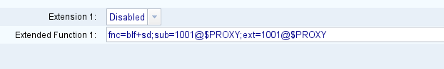
Please note that if you would like the ability to dial the extension number registered to the IP Uni, you will need to navigate to ‘Services’ (purple tab), then ‘Calls’ which is located at the top of the interface, then set ‘Call Answering Mode (SIP1)’ to ‘Automatic’ using the drop down list. You can then go ahead and apply the changes by clicking the ‘Apply’ button. You should now be able to dial ‘200’ from the KX-HDV130 and the Uni will automatically answer the call.

Panasonic KX-HDV130 Configuration:

You will need to start by finding out the IP address of the phone by navigating to ‘Menu’, ‘System Settings’, ‘Status’, ‘IPv4 Settings’, then ‘IP Address’. The IP address should then be displayed on screen e.g. ‘192.168.x.xx’.

You will then need to enable access to the web interface before you can web browse to the phone which can be done by navigating to ‘Menu’, ‘Basic Settings’, ‘Other Option’, ‘Embedded Web’ and then changing this setting to ‘On’. You can then go ahead and web browse to the phones IP address via a web browser of your choice e.g. Google Chrome.

When you browse to the IP address of the phone, you should be prompted to enter a username and a password. The default username is ‘admin’ and the default password is ‘adminpass’. Again, it is highly recommended that you change the default password before using the device.

You will need to click onto the ‘VoIP’ tab located at the top of the web interface, then click onto ‘Line 1’ which is located on the left hand sidebar under ‘SIP Settings’. Enter ‘200’ in the ‘Phone Number’ field, then the IP address of the IP Uni under ‘Registrar Server Address’. You will also need to enter the IP address of the IP Uni under the ‘Outbound Proxy Server Address’ and the ‘Service Domain’ fields. For the last two steps of the configuration for the KX-HDV130, enter ‘200’ in the ‘Authentication ID’ field and leave the ‘Authentication Password’ field blank.

That’s the end of the main configuration process for the 2N Helios IP Uni and the Panasonic KX-HDV130.

If you have any questions, please send them to matthew@provu.co.uk

How to connect a Snom V2.0 Expansion Module to a D315/D305 Phone

screenshot-from-2016-11-07-134102

Connecting a V2.0 Expansion Module to a D315 or D305 phone:

If you have an Expansion Module V2.0 (discontinued product), you can use it with the D315 and D305 phones by connecting it to the phone‘s EXT connector , but please note and make sure to heed the following warning:

Warning: Attach the module to the phone with one screw only, using the top hole. Using a screw in the
bottom hole will damage the phone‘s PCB!    screenshot-from-2016-11-07-134214

How to firmware upgrade a Konftel 300Wx

Below is a step-by-step guide on upgrading a Konftel 300Wx using the SD card method. You will need to download the firmware file found here: http://www.konftel.com/Support/Upgrade and put it in the root of a Fat32 formatted SD card. Once you have done this, follow the steps below:

Power on the device, once it has booted up insert the SD card. Then go to > Settings > Upgrade Mode:

14964212_1151093798331458_1604429113_o

The phone will enter the Firmware upgrade mode and prompt you to run the PC Suite to start the upgrade:

14954390_1151093738331464_755233396_o

Instead, press the button on the bottom left corner of the phone, the device will then start reading from the SD card:

14958125_1151093711664800_1899115787_o

If the phone finds the upgrade file on the SD card, the screen will display the new firmware version. To start the upgrade, press OK. It will then start “Erasing” the firmware and upgrading to the new version. Do not power it off while the upgrade is in progress.

14907861_1151093694998135_117459166_o14971549_1151093691664802_1085066309_o

After it has finished “Erasing” the firmware upgrade is complete, click “Ok” at this message and you have completed the upgrade successfully. Once the unit has rebooted fully you can remove the SD card:

14959057_1151093668331471_1373214390_o

If you are still having problems please contact our support team.

Pairing the VTech VSP500A & 601A with the VTech VSP726A & VSP736A

In case you didn’t know, the VTech VSP726A and the VSP736A phones can be paired with both the VSP500A Cordless Headset and the VSP601A Handset, this Is how:

Pairing the VSP500A  Cordless Headset with both the VSP726A and the VSP736A Phones:

  1. On the Desk Phone click on Menu > User settings > DECT Headset, at this point lift the Cordless Headset off of its charging dock and place back down and then selected “Register” on the Desk Phone.
  2. This will search for the Cordless Headset and “Registration Successful” will appear on the screen of the Desk Phone. They are now registered and ready to go.

Pairing the VSP601A Handset with the VSP726A and the VSP736A Phones:

  1. (VSP726A and VSP736A has built In base station) Once both the DECT Handset and the Desk Phone are turned on, go to the DECT handset go to Menu > User Settings > Registration > Handset.
  2. “Which device do you want to register the handset to?” will come up on the screen select Desk phone, this will then tell you on screen what to do with the Desk phone.
  3. Once you follow the steps on the Desk phone you’ll get to a screen that says “Register” and “De-register”, Press “Next” on the Handset and “Register” on the Desk Phone.
  4. You need to press the “#” key on the handset, this I will then start searching for the base station, once found It will display “Registration Successful” on the screen. You have now registered the DECT hand set with you Desk phone

For a more detailed step by step use the user manual below:

http://ukbusinessphones.vtech.com/themes/md/downloads/VTech_VSP726A_User%20Guide_Rev-1.pdf

If you are still having problems please contact our support team.

How to pair the VVX D60 wireless handset with a VVX phone

Before following this guide you need to make sure that the firmware version is on 5.4.3 or later, otherwise it will not detect the wireless handset to pair to.

There are three different ways to register the handset with the VVX phone, there is manual pairing, auto pairing and a PC port pairing. But here is what we found easiest:

1) Start by plugging the Ethernet cable and power supply (if necessary) into the back of the D60 base > plug the VVX phone in like normal using Ethernet into the LAN port of the phone.

Before you can pair the two devices you need to make sure that the VVX-D60 feature is enabled to do this:

2) On your VVX phone go to Settings > Advanced (this will then ask you for the administrators password to access the menu) > Scroll down till you find VVX-D60 Configuration and select it > Select VVX-D60 Profile and then select Enable.

Now that the VVX-D60 feature is enable you will need to pair the base station with the VVX phone, there are three different ways to pair the two devices but the easiest way that we found was the “Auto-pairing” option, to do this:

3) On the VVX phone go to > Settings > Features > VVX-D60 Configuration, from this screen select > Base Station and then > Auto-pairing > Select a Base-Station and finally select > Pair.

The two devices should now be paired with one another, for a more detailed explanation use the link below. If you’ve followed the guide and still are having problems, contact our support team.

http://support.polycom.com/global/documents/support/user/products/voice/vvx_d60_ug.pdf

Snom D710/D715 – DND Display Differences

For Snom phone models 710/715, there is a slight display difference when using the DND mode on phones using the 8.7.5.35 firmware. With previous versions of firmware, when DND was active, a banner would be displayed across the screen; with 8.7.5.35 and newer versions, this is not the case. Instead, it just displays a small message.
no dnd
In order to fix this problem:
1. Copy all of the following URL: 

PhoneHasTextMessages PhoneProvisioningFailed

2. Replace “phoneIPaddress” with that of the phone you are using.

3. Enter into your web browser and it should fix the problem. The DND message should now look like the one below.

dnd