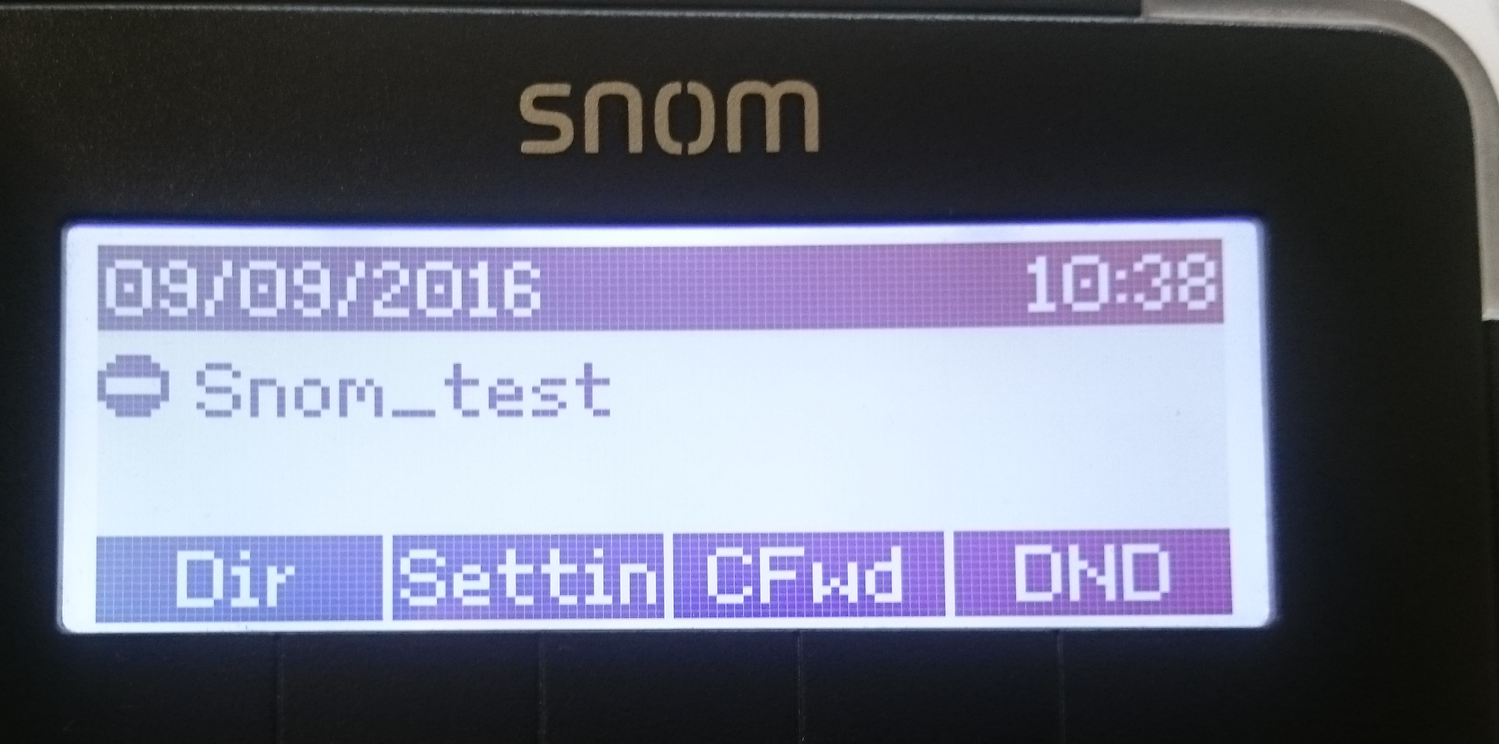
For Snom phone models 710/715, there is a slight display difference when using the DND mode on phones using the 8.7.5.35 firmware. With previous versions of firmware, when DND was active, a banner would be displayed across the screen; with 8.7.5.35 and newer versions, this is not the case. Instead, it just displays a small message.
In order to fix this problem:
1. Copy all of the following URL:
If you have a Konftel 300Wx and an IP DECT 10 and are having problems registering the two, here is a simple step by step guide on how to do so:
1) go to the web interface of the IP DECT 10 > go to the “Server” tab on the left and “add new server” > add the IP address/URL of your pbx to the registrar box and then save.
2) go to the extension tab at the left side and add a new extension by clicking on any of the numbers 1 – 20 in the IDX column> add the extension number, authentication user name and password from your pbx, tick the box at the top right that says add handset and then save.
3) tick the box next to the extension you just added, then click on “start SIP registration” below the extensions table, now go onto the handset tab at the top, next to extensions, click on the IPEI default of 0000000000000 and change “Alarm Line” to the extension number and press save.
4) tick the box next the handset you just added, then click on “Register Handset” under the handset table.
5) on the handset go to menu> settings > DECT > register > press BASE 1, then it says “ENTER PIN CODE” enter “0000”.
6) Device will start searching and should say success on the screen. Now refresh the web interface and the IPEI should have a long digit number instead of 0000000000000. it will now be registered and working.
If you follow the guide above and still have problems, contact our support team.
If you have a Sangoma Vega 100G, 200G or 400G gateway connected to a BT ISDN line, you might find sometimes that the Caller ID coming in on phone calls is missing the leading zero. So you might receive a call that shows as being from ‘7123456789’ instead of ‘07123456789’.
The reason for this is that often an ISDN line doesn’t send the national or international dialling codes but instead a flag in the ISDN message called Type-Of-Number. This flag can usually contains ‘national’ or ‘international’ as a value which is intended to tell the device connected to the ISDN line (i.e. an ISDN PBX) to add the correct codes to the start of the Caller ID depending on the location/country it is in. The point of this is that these numbers might not be the same in different areas or countries.
To make the Vega put these numbers in, change the following settings found in the SIP -> Advanced SIP Settings page:
National Prefix = 0
International Prefix = 00
Then the gateway will add these numbers as long as the ISDN line includes the TON flag (which it should do if it is not sending the 0/00 in the Caller ID).
We have had an enquiry come in about how to wire in a tamper switch without an I/O module or a Wiegand module. I must admit I thought this was strange at first, given that I always thought it was fairly simple to do. It turns out it is but it is also easy to overcomplicate.
Make no mistake that 2N’s ideal setup would be a tamper switch connected to either an I/O module or a Wiegand module – every single piece of documentation I have found shows it connected in this manner. The idea is that it has 2 switches – we’ll call them switch 1 and 2 – with switch 2 connecting to the I/O module and back into the Verso, where it is recognised as a tamper switch, and switch 1 connecting to, for example, a 3rd-party alarm system, where it is recognised as a generic input that activates whatever the alarm system is programmed to activate.
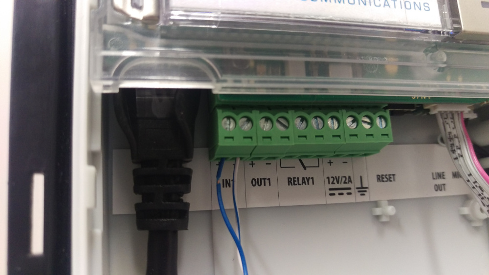
The Verso however has its own generic input, into which you can wire switch 1 and have it behave as exactly that – a generic input.
Please note: in order to make use of a tamper switch in any way, you must have at least the Enhanced Integration Licence.
What you will need:
A 2N Helios IP Verso base unit with or without camera – 9155101C or 9155101
A tamper switch – 9155038
2 lengths of thin wire, about 6 inches long should do it – the lengths of wire I picked up for this demonstration are closer to about 6 feet.
A small screwdriver
Whichever other modules you wish to connect to the Verso – we have just an infopanel on our demo one.
The relevant mounting boxes and/or frames – we are using a 2-module flush-mount box and frame.
A computer on the network to do the programming.
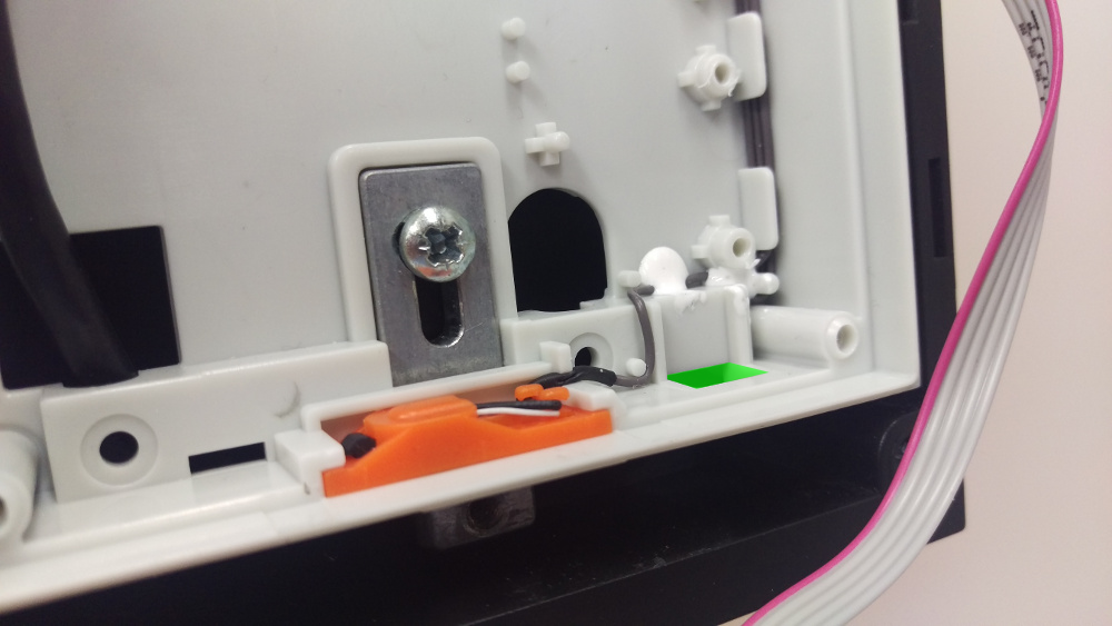
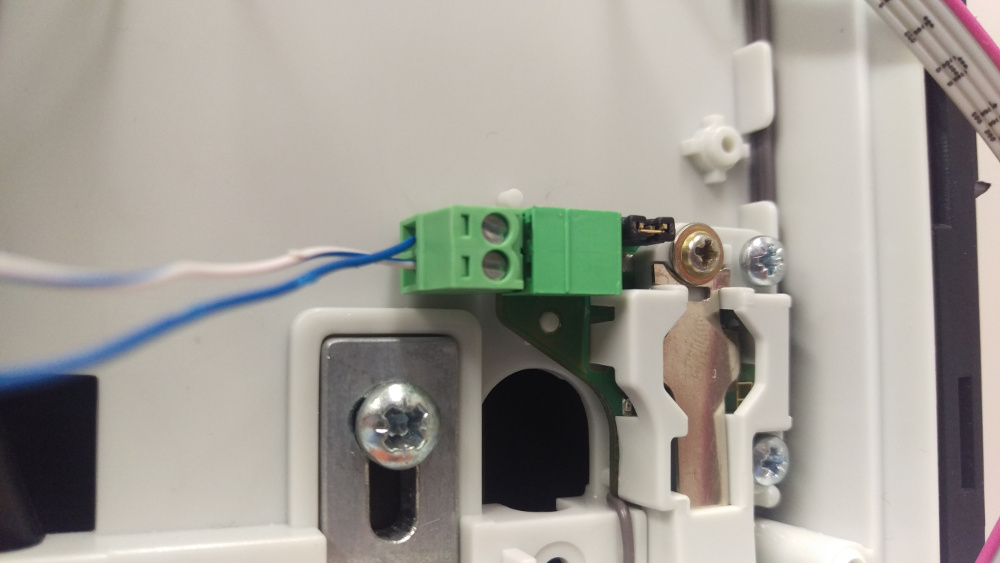
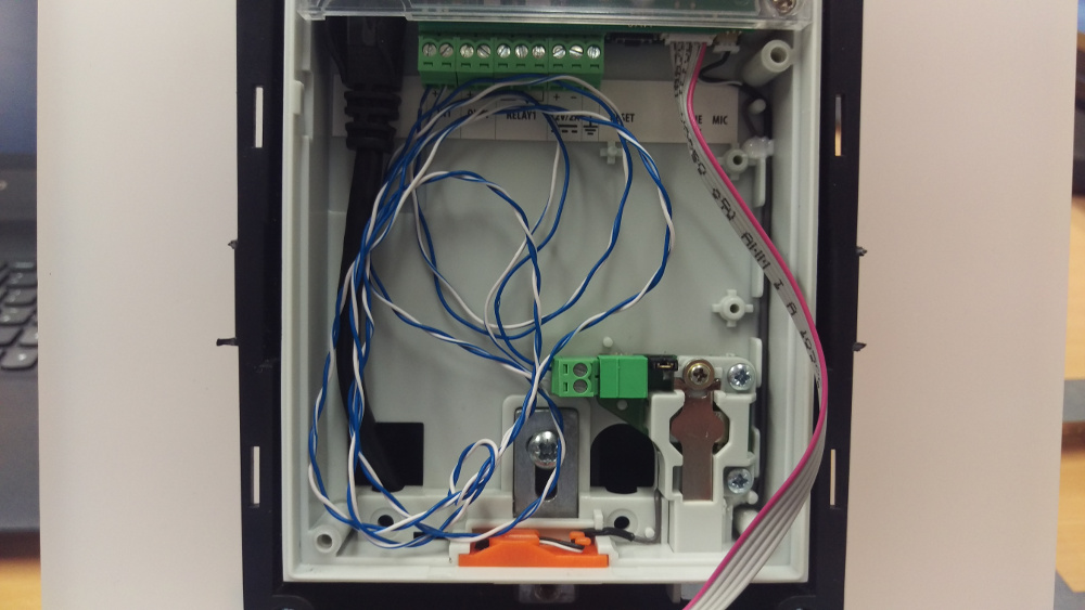
This is the bottom of the backbox and the tamper switch is inserted where the green square is……the tamper switch is inserted like so……and screwed in.
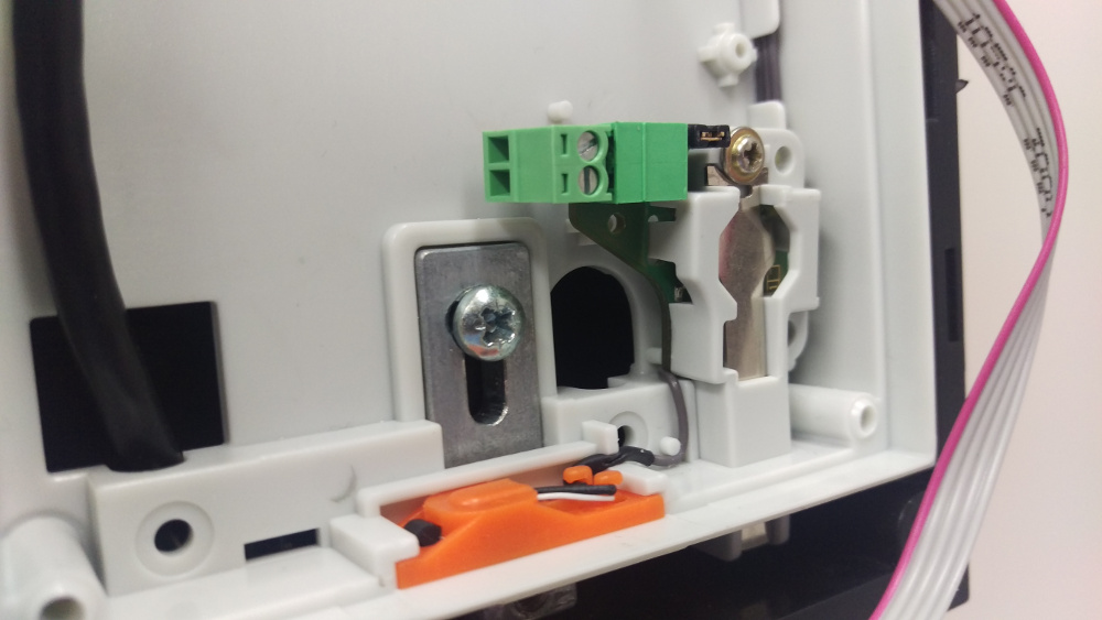
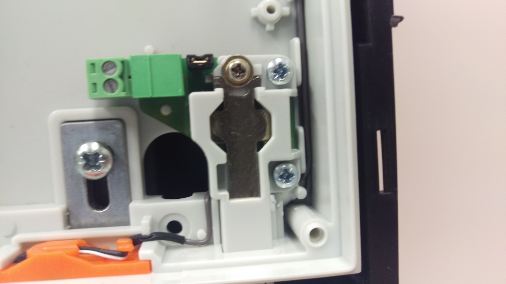
The tamper switch then needs wiring in via that little green terminal block on the left:
Fairly simple, just insert the wires into here……and here.Your wires will ideally be a bit shorter than this!
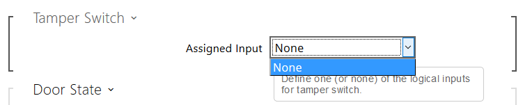
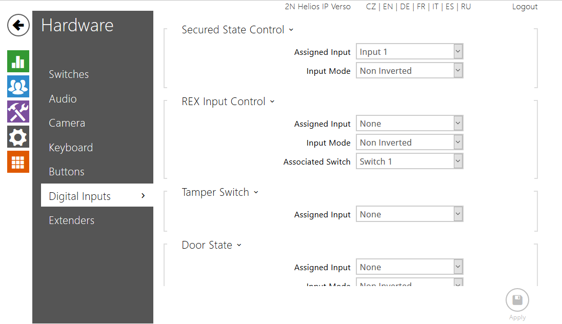
As mentioned earlier, because of the way it’s wired in, the Verso doesn’t know it is communicating with its own tamper switch, so the below is what you’ll see in the web interface when you try and program it as a tamper switch:
To run a quick demo of it working, I told the Verso that its Secured State Control was controlled by the status of input 1 – all this does short of any programming is activate a red LED next to the camera in the shape of a padlock – without the Enhanced Integration Licence this is all it will be able to do.
How to set the Secured State Control.
By using a screwdriver to press and depress the tamper switch, I was then able to turn the red LED on and off.
Please note: If you are using a tamper switch in this way you will not be able to wire anything else, such as an exit button, into the same input on the Verso. The only way to use an exit button without buying an I/O module will be to buy a security relay.
I faced a strange problem when trying to SSH onto the Vega from my Debian desktop… the connection sat there and just timed out. I could telnet to the port and was prompted with SSH-2.0-Mocana SSH but nothing was happening with SSH.
I did some digging and found that there was an incompatibility with the algorithms in use in the default configuration.
You can get around this by specifying the following SSH options:
It has always been possible to manage firmware upgrades using our online phone management portal, ProSys. Support staff can do this very quickly by selecting from a drop-down box of available firmware on the portal.
What happens if you want a newer firmware, or just one which isn’t listed in the drop-down (yet!)?
Well, fortunately, it is possible to provide a custom setting in most cases to allow you to select the firmware you wish to provision to a device.
Proceed with caution…
You can use the “Quick entry” to add configuration settings to an individual device.
This allows you to add (key, value) pairs to the provisioning settings, giving you the power to provision firmware directly.
You can connect to the TG582 router’s command line interface using telnet which gives you a great level of control over this router. You need to be connected to the LAN side of the router, you cannot do this over the Internet (unless you are VPN’d to a PC on the local network the router is on). The default login username is “Administrator” (yes. uppercase ‘A’!) and the password is the web interface password (blank by default).
You will need to have the firmware file hosted on a web server somewhere, lets say the URL for this is http://myserver.com/tg582firmware.bin. The server this is hosted on doesn’t need to be on the local network with the router as long as the router has a working Internet connection.
Iissue this command in your router’s telnet interface:
It may ask you for some other options, just leave them blank (by pressing the return key).
Then your router will download, reboot & upgrade itself.
Note: on the new TG588 & TG589 routers there is no need for this as you can simply upgrade firmware in the web interface. Some of these do have a command line interface but it is totally different to the TG582 and doesn’t seem to be very useful (yet).
We launched the Algo 8188 SIP Ceiling Speaker back in January which joined our expanding range of Algo paging and alerting devices. This SIP ceiling speaker can integrate natively with Polycom™ Group Page for overhead announcements.
The 8188 provides additional coverage in common areas or where sound reinforcement is needed, like classrooms, lobbies or hallways. The 8188 can also be configured to join Polycom paging groups or zones.
Polycom Group Page has no dependency on a SIP server and therefore the 8188 also integrates seamlessly with Skype™ for Business/Lync™.
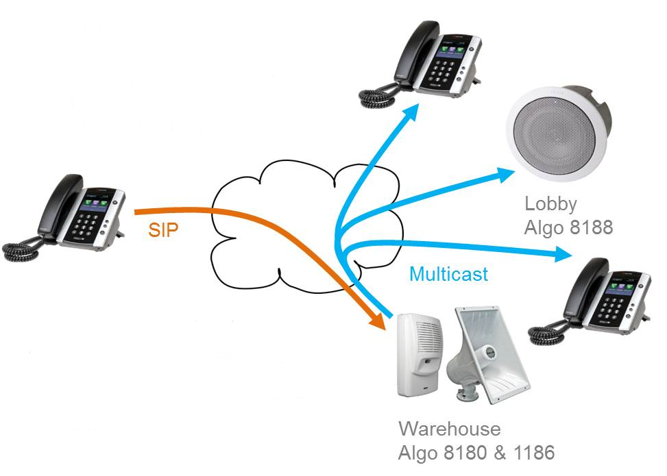
SIP Initiated Group Paging
Polycom VVX phone calling Algo 8180 SIP alerter which simultaneously launches a local Polycom Group Page.
Algo paging endpoints have multicast broadcast capability. While paging or alerting, they can simultaneously multicast over the network.
How To Setup LDAP/Active Directory phonebook on a Panasonic HDV (130,230,330) SIP phone
LDAP (Lightweight Directory Access Protocol) is commonly used with SIP phones to store contact lists or phonebooks. Many modern SIP phones can connect to an LDAP server and it is my recommended method of implementing a shared phonebook (simply because of cross-device support).
I will assume you already have a working LDAP server set up. On a Microsoft server, LDAP is called Active Directory. OpenLDAP is commonly used on open source based systems. Both work the same from the phone’s point of view.
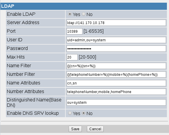
Here is a screenshot of some example settings from a HDV330 phone.
These settings are fairly standard in SIP phones (or anything that is doing LDAP searching). Without going in to too much detail, key points are:
Server Address: this has to include the protocol name ‘ldap://’ at the start. Or ldaps:// for ldap over ssl
Port: normally 389 for ldap
User ID: you have to specify a username & password. The phone will not connect anonymously. The user id has to be the full DN of the user. Exactly what this is depends on how your ldap server is setup
Name/Number Filters: these settings contain the searches that will be performed depending on whether a name lookup (the user typed in letters) or a number lookup (the user typed in a number). What goes in here depends on your ldap server set up
Name/Number Attributes: these are the attributes within your ldap database that you are using to store names and telephone numbers in
Base DN: where to start the search in your ldap directory (ldap is hierarchical so objects above this base will not be seen by the phone)
DNS SRV: this is used for service discovery, if you don’t know what it is then leave it set to No!
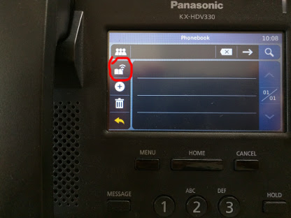
Note – you must specify a username & password, these phones will not bind anonymously. I wouldn’t recommend running an ldap server like that anyway as you are leaving yourself open to getting all your contact’s information stolen!Now on the phone itself, find the phonebook option and select it. You will probably be shown the internal phonebook by default, press the option to switch to ‘shared phonebook’. On a HDV330 you press the button circled in red in this photo:
Then you can use the search box to type in a name, matching entries will be displayed:On phones with programmable keys, you can configure a key for shared phone book. Set the key type as ‘phonebook’, set the parameter to ‘2’ (for shared phonebook) and give it a label if required.
You will need to open up the 2N IP Audio Control Panel on your PC, have your 2N Net Audio Decoder connected to your network and a functioning Snom D765. Click ‘Destination & Zones’ using the left hand sidebar, then click Create RTP destination again on the left hand sidebar. You can give the RTP destination a more meaningful name if you wish rather than ‘RTP destination 1’. For better quality sound, you should choose Linear PCM 16 bit Stereo (44.1kHz), then choose the IP address e.g. 239.255.1.10, then set the port number to 7000 and leave TTL as -1. You will then need to save your configuration using the ‘Save configuration’ button located near the top left hand side of the window.
After you have followed the previous steps, you will need to navigate to ‘Sessions’, then right click in the centre in the white space, and click ‘Create session’. On the left hand side, providing you have some media ready such as an Internet radio station, you will need to drag this into the new session you just created. The Internet radio station will then be displayed on the session. Finally, you need to drag the RTP destination you created earlier on, and drag this onto the ‘DESTINATIONS’ section on the session. That’s the main configuration complete for the 2N IP Audio Control Panel (2N Net Audio Decoder). The next step is to configure your Snom phone for multicast.
You will need to obtain the IP address of your Snom phone by pressing the Menu key, pressing key number 6, then pressing key number 2. This will show the System Info which will display the IP address of the phone e.g 192.168.1.64
Web browse to the IP address of the phone using your web browser. You may be prompted for a username and password which you may not know about. If this is the case, you will need to consult your system administrator. By default, there is no username and password set, if this is the case, you should see the Snom web interface.
That’s the end of the configuration process. All you need to do now is go back to the IP Audio Control Panel, click ‘Sessions’, then ensure MASTER CONTROL and Internet radio station is set to on and the volume bar is up. The radio station should now page to your Snom phone.
If there are any questions, please email matthew@provu.co.uk


 Then you can use the search box to type in a name, matching entries will be displayed:
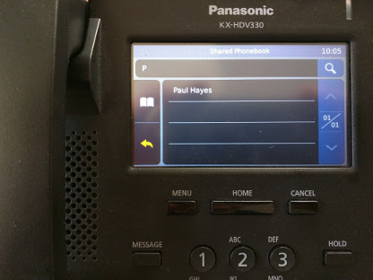 On phones with programmable keys, you can configure a key for shared phone book. Set the key type as ‘phonebook’, set the parameter to ‘2’ (for shared phonebook) and give it a label if required.