Updated 09/02/2018 – Luke Warby
*RTX4022P can not be set up in Daisy Chain with 3rd party devices such as Gigaset and Yealink*
Updated 10/01/2014 – Chris Wright
Below are some instructions that will help in registering a RTX repeater with Gigaset Base station.
DO NOT PLUG IN THE REPEATER UNTIL INSTRUCTED
1. Set the range extender up near the Gigaset Base Station, you can move it to its final
destination later.
2. Turn off Eco Mode through the Gigaset handset, go to Settings – Eco Mode. Untick the boxes if necessary
3. Turn on Repeater Mode through the Gigaset handset, go to Settings – System – Repeater Mode.
(If you are using firmware 42.194 or greater, you will need to disable the Encryption setting at this stage rather than enabling Repeater mode. More info here)
Updated 28/03/2018 – Jordan Carr
*RTX4022: press the button on the back of the repeater for 5 seconds instead of plugging the power in*
4. NOW PLUG THE POWER INTO THE RTX 4002 for 5 seconds and turn it off again; then turn it back on.
Note: The LED on the RTX 4002 slowly flashes showing that it is now in registration mode.
This should be a single flash, if it is a double flash please go back to Step 1 and retry.
5. Turn on Registration on the Gigaset Base Station, by either:
a. In the web GUI, go to Management > Miscellaneous > Start Registration’
b. On the Gigaset Base Station, press and hold the PAGE/FIND button for approximately 3-5 seconds
Note: The LED on the RTX 4002 flashes quickly to show that it is in ‘learn’ mode.
6. On the Handset – Key in X* – where ‘X’ is a number between 2 and 7. (This relates to the repeater number – the first repeater is number 2 as the N300 is the first link (1).)
Then press the green SEND button.
The LED will stop flashing for about 5 seconds; press * again to confirm the pairing. The LED should now show a steady light without flashing.
Note: If the LED goes back to flashing quickly then the new settings have not been saved or accepted by the RTX 4002. Repeat item 5. If the LED goes back to flashing quickly again then repeat item 5 with a different X.
7. Now position the RTX 4002 where required, ensuring that it is still within range of the Gigaset Base Station.
** If you hear a chirping/beeping noise when on call within range of the RTX, you may have enabled the verfication tone. For instructions on turning this off, please view our blog post**
 :
: :
: :
:
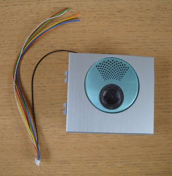
%> <%popup(20110603-DSCN0395.JPG)